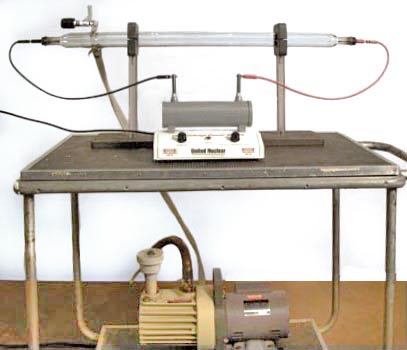
Figure 1: Large spectrum tube setup
Above is a demonstration of proper use of the vacuum tube provided by Nick McCabe.
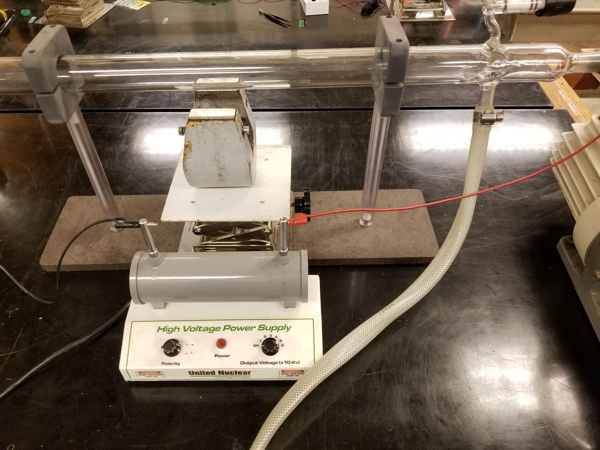
Figure 2: Large spectrum tube setup with magnet in place
Equipment:
- Large spectrum tube [underneath glassware]
- Vacuum Pump [with coin and feather drop]
- High Voltage United Nuclear Power Supply [Cabinet K3]
- Large Magnet [Cabinet F3]
- Small Magnets [Cabinet F3]
Demo:

Figure 3: large spectrum tube striations
To begin this demo, first turn on the power supply to 10-20 kV. This applies a voltage to the electrodes on either side of the gas, producing visible cathode rays. Increasing voltage beyond this point increases the intensity of the rays, but has no effect on the physical principles. Next, turn on vacuum pump to decrease the pressure within the tube. This step will change the wavelength of EM radiation emitted with a visible oscillation of pressure waves within the gas. These oscillations are more easily visible near the opening in the tube where the vacuum pump is connected. See Figure 3 above for an example of this resonance.
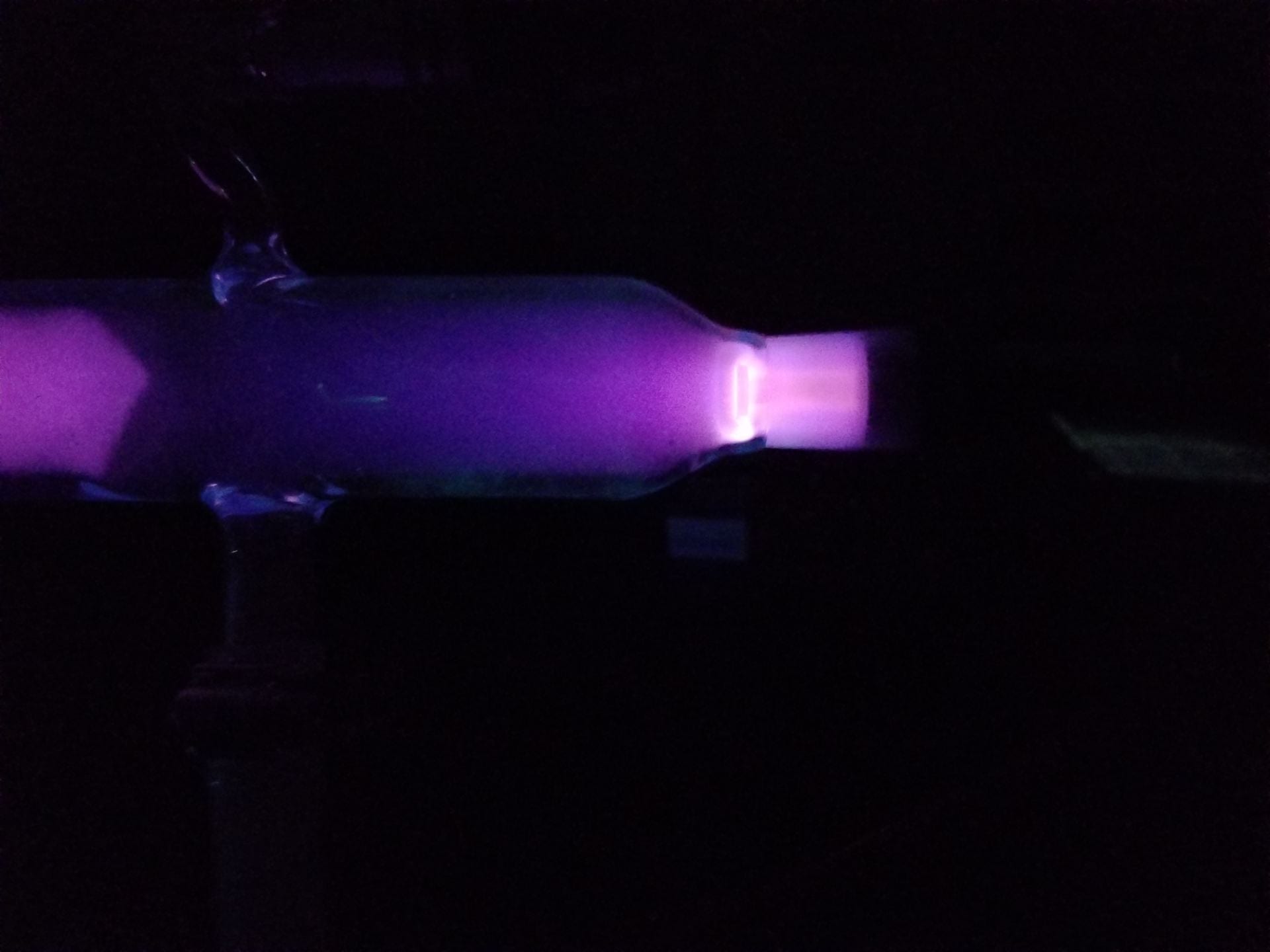
Figure 4: Small magnet on the anode
With the tube evacuated, one can hold a magnet to several areas of the tube to produce distortions of the cathode rays. Figure 4 above shows an example of this, the result of a small neodymium magnet held placed on top of the tube near the anode.
In addition, one can place the provided large magnet below the tube in several orientations to produce yet more distortions. Figure 5 shows the result of this large magnet resting below the tube, with it’s magnetic field perpendicular to the path of ions.
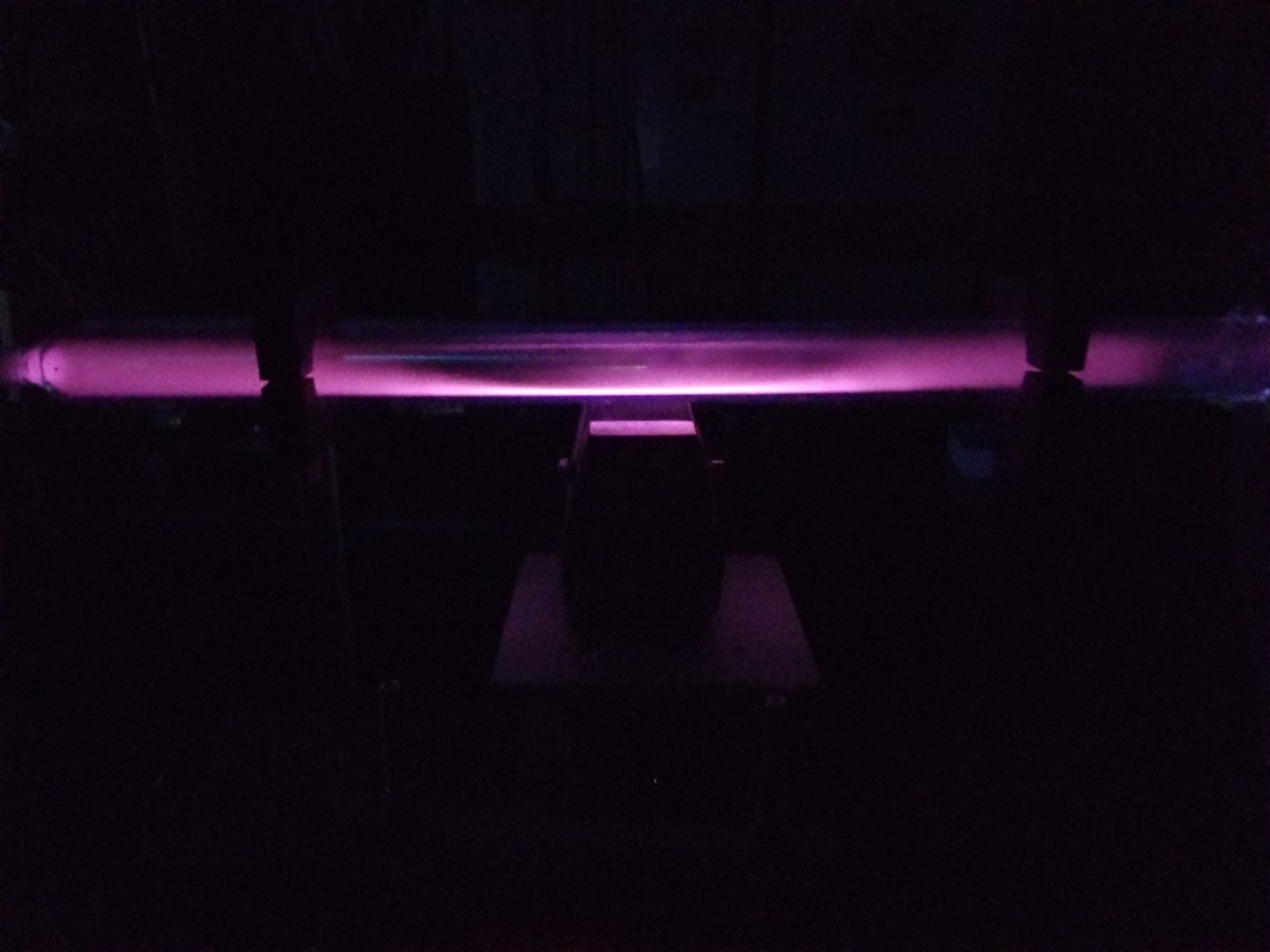
Figure 5: Large spectrum tube with large magnet underneath, perpendicular magnetic field
One can also turn this magnet 90 degrees in the same vertical position to produce the effect seen below in Figure 6.
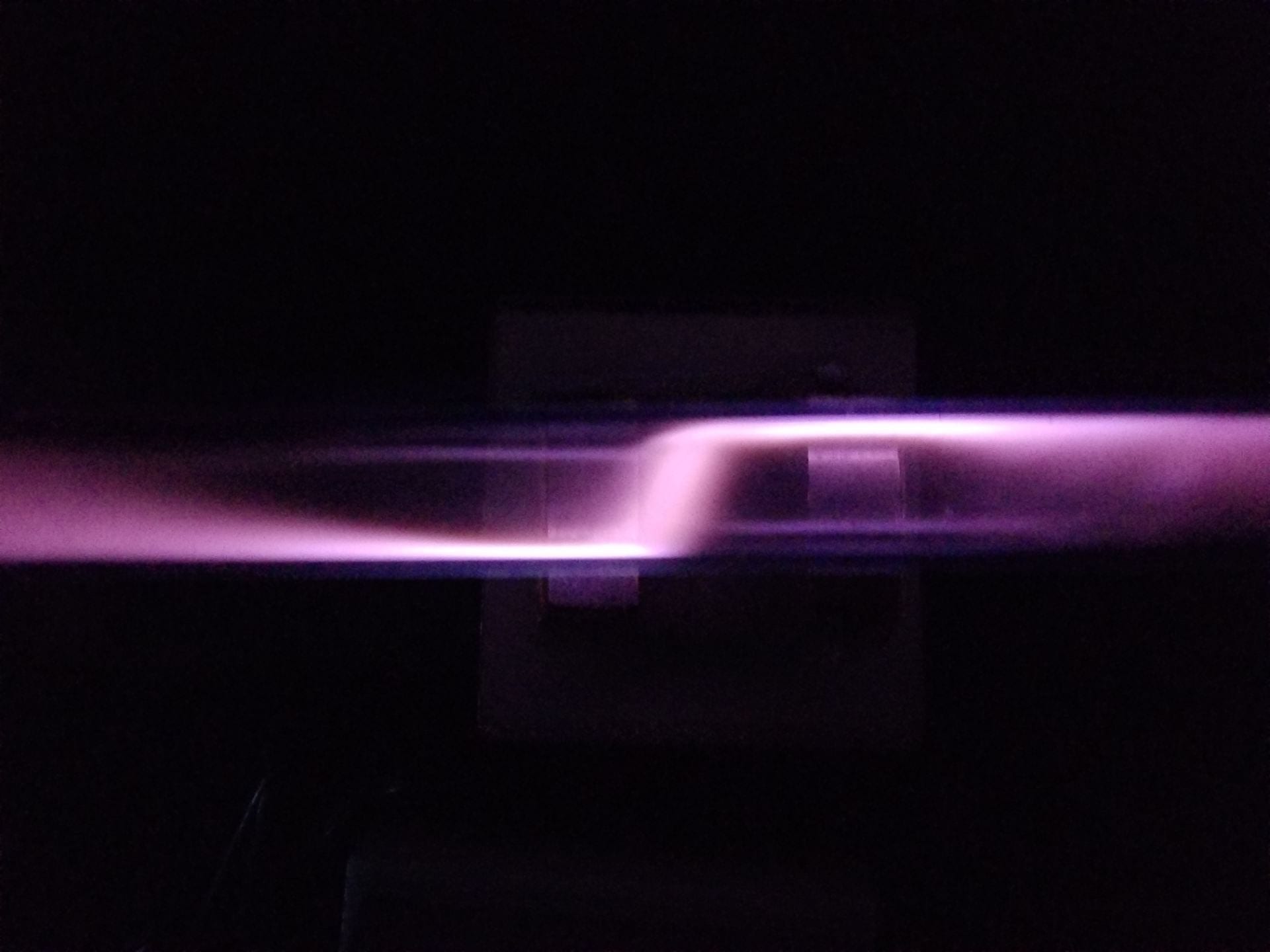
Figure 6: Large spectrum tube with large magnet underneath, parallel magnetic field
Explanation:
To begin the explanation of this demo we first need a diagram to label each piece of the tube where different phenomenon occur.
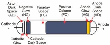
Figure 7: Cathode ray tube diagram from Wikipedia
First we apply a large voltage across the tube using the small metal inserts found on either end of the tube. This voltage across the tube creates a large electric field within the tube, pointing from anode towards the cathode. In this electric field, positive charges will experience a force towards the cathode, while negative charges will be forced towards the anode. Near the cathode we expect a large number of electrons to be emitted due to the current from the applied voltage. Because electrons are negatively charged, they’ll experience a Lorentz force in the opposite direction as that of the electric field within the tube. This force will cause a bulk movement of electrons away from the cathode.

This constant force on the electrons would lead us to believe that these particles accelerate until they reach the anode. However, this isn’t the full picture. Within the tube there are air molecules blocking the path of the electrons. Each electron will only be able to travel so far before colliding with an air molecule and scattering off in another direction. We call the distance they travel before collision the mean free path. The mean free path is dependent on the density of air molecules, and tells us how fast we expect the electrons to travel on average before a collision with an air molecule. We are then able to model these collisions as a dissipative force which counteracts the Lorentz force shown above.
A useful analogy can be seen in the act of skydiving. Initially the diver falls unimpeded, acted on only by the force due to gravity. This unbalanced force causes the diver to accelerate downwards towards the earth. However, as their speed increases we must account for air resistance. This resistive force is speed dependent and will continue to grow as their speed does. Eventually the two forces will reach an equilibrium with the diver sailing downwards at their terminal velocity. It is important to note that the diver stops accelerating once these forces balance, but continues to fall at the same velocity.
The resistive force due to air molecules within our cathode ray tube is quite similar to that of the skydiver. The Lorentz force pushes the electrons towards the cathode, but the electrons are only able to accelerate for so long before bumping into an air molecule.
Now we are interested in where the kinetic energy of the electron goes once it bumps into the air molecule. Once the electron scatters off the air molecule, some of its energy is transferred to the air molecule. This brings the molecule into an excited state. However, excited states are usually unstable as it is energetically favorable to be in their ground state with little potential energy. Due to this energetic favorability, the molecule will then transition from its excited state back down to the ground state. In this process, the molecule will emit a photon with the same amount of energy as the electron gave it through scattering. At this point the tube should emit no visible light because we have yet to evacuate the chamber. With a larger number of air molecules within, the electrons aren’t able to reach a large enough terminal velocity to allow for the air molecules to radiate photons in the visible light spectrum.
Now, we partially evacuate our tube of the air within. By reducing the pressure at constant volume and temperature, we have reduced the number of air molecules in the tube.

By reducing the number of molecules, we’ve also increased the mean free path of electrons traveling within the tube. With a larger mean free path, the electrons are able to gather more kinetic energy before collision with an air molecule. The electron then transfers more energy to the molecule it bumps into, allowing it to enter a more energetic excited state. The molecule then drops down to its ground state as it emits a photon. This photon has a higher energy as a result of the increased energy from the scattered electron. Once the tube is evacuated enough, these photons will be in the visible range and can be seen within the cathode ray tube.
The primary physical concept behind the function of this tube is ionization of air molecules within. To better understand the reason behind spacing of the various regions we’ll observe the bulk flow of electrons once the external voltage is applied.
Near the cathode we expect a large number of electrons to be emitted. The applied voltage creates an electric field pointing away from the anode and towards the cathode. Because electrons are negatively charged, they’ll experience a force in the opposite direction as that of the electric field within the tube. This force will cause a bulk movement of electrons away from the cathode.
Decreasing pressure within the tube is achieved by reducing the number of air molecules inside the tube’s fixed volume. With a lower density of molecules, the electrons are able to travel further into the tube before scattering off and ionizing those molecules. This effect explains why the negative glow region extends when the pump is on as the Faraday space with no light emission recedes from the cathode.
Notes:
- This demo is extremely dangerous and should only be operated by demo room professionals
- The voltage supply runs up to 50 kV and may not have a reliable current limit
- Use proper PPE such as insulating electric gloves and insulating floor mat
Written by Noah Peake