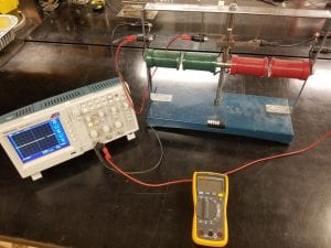
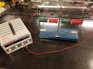
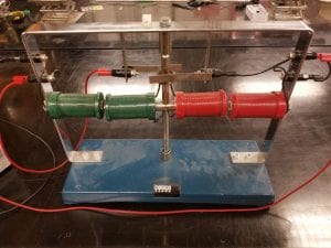
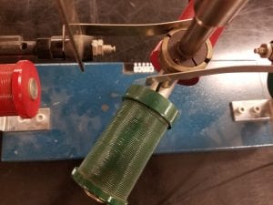
This is a simple, large model used to generate current (Figure 1) or to work as an electric motor (Figure 2). The magnets, brushes, coils, and terminals are clearly shown to explain the operation of a generalized motor.
Materials:
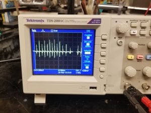
- Oscilloscope — Visualizes current produced by input rotations of the motor. Using this visualization allows students to see the time dependence of the current produced, and how it depends on the motor’s position. This is show below in Figure 3 with the desired waveform.
- Multimeter — Used in the ammeter mode to detect current, this device will show that the generator produces a current when spun by hand.
- Motor — This apparatus will be used as both a motor and generator depending on the setup. It consists of several electromagnets, a rotating axis, and brushes to ensure continuous electrical contact.
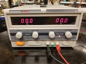
- Dr. Meter power supply — This device will supply a variable DC voltage to the motor in order to drive it at various rotational speeds.
- Banana jacks — One set of banana jacks is required to connect the motor to either the oscilloscope or DC supply
Setup:
After the initial setup, the oscilloscope may need slight adjustments to provide a good view of the waveform. The pulses are best seen by setting the channel one voltage scale to 200 mV and the timescale to 500 ms using the scale knobs located on the lower half of the oscilloscope. With the above circuit, and the oscilloscope set as described, simply turning the motor by hand will produce a visible voltage on the oscilloscope. It becomes visible that the spikes occur as the electromagnets reach their closest point. The faster the motor is spun, the larger the spikes in voltage become.
Setup for the driven motor demo becomes very simple at this point, because only one modification is required to switch from generator to driven motor. The only change necessary is connecting the banana jacks that previously went to the oscilloscope to the DC power supply instead. The same circuit in Figure 7 applies, except that we’ve swapped the oscilloscope for the power supply. Now turn on the power supply and turn up the applied voltage to 9 volts using the course adjust knob. The motor will need a small push to get started, but will continuously spin after this initial push. The motor will spin with a voltage above 9 volts. It is important to keep the supply below 12 volts in order to prevent damage to the motor apparatus.
Notes:
The motor experiences much less drag when rotated counter-clockwise. This makes it the desired rotation direction for both hand turning and when driven by the DC power supply.
Only use a maximum supply voltage of 12 V in order to prevent damage to the motor.
Other electrical devices near the banana cables will generate enough background noise to completely cover the generator’s pulses. Keep the banana cables away from other electronics to produce the cleanest signal.
If the oscilloscope still has noise, it is likely due to a loose banana cable to the motor. This can be fixed by checking the two connections between oscilloscope and motor, or by connecting a small capacitor in parallel with the two banana cables in the oscilloscope.
Explanation:
The motor works using a clever combination of simple physical concepts. Firstly, it relies heavily on the fact that opposite magnetic poles attract each other. Most students will have an intuitive understanding of this if they’ve ever played with bar magnets before. This idea is incorporated into the motor through the four electromagnets. These are the four separate green and red cylinders visible in the motor apparatus.
Electromagnets function by sending current through a wire loop which creates a magnetic field within the loop. This concept is shown below in Figure 8.
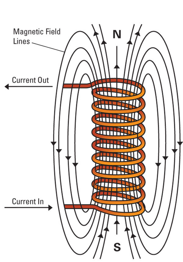
Figure 8: Electromagnet Operation from Northeaster University
Electromagnets rely on the basic concept that moving charges create magnetic fields around them. Knowing this, we can then send current, a flow of charged electrons, through a wire to create the desired magnetic field. One important note with electromagnets is that the direction of magnetic field depends on the direction of current flow. If the current were to be reversed in the diagram of Figure 8, the magnetic field would respond by switching directions after a short amount of time. This switching of magnetic field direction is very important to the operation of our motor.
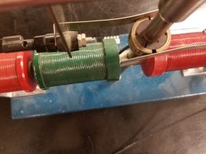
The practical aspect behind the design of this motor is being able to switch the current to two of the electromagnets with the right timing to ensure continued motion. This is accomplished using brushes that keep a continuous electrical contact. This creates a connection between a rectangular metal tab, and circular rotating metal disk. The disk is divided into two half circles, with each half circle connected to one of the spinning electromagnets. These connections are shown in detail in Figure 9 below.
With the constant connection between the brushes, current is always allowed to flow through the system of four electromagnets. To describe the process as a whole, we first define several vocabulary terms. The rotor is the portion of the motor which rotates on the central axis, consisting of the two central electromagnets and the connections made between them. The stator is the stationary portion of the motor, consisting of the other two electromagnets and connections which supply them with current.
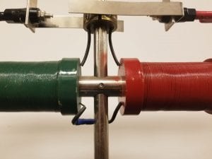
The process begins with the rotor set spinning, initially done by hand. Current flows through all electromagnets in such a way that the magnetic fields are aligned and the magnetic fields attract. This creates a rotational force that attracts the rotor electromagnets to the stator electromagnets. As the electromagnets get closer, the force increases due to the increasing overlap of magnetic fields. Next, the magnets are aligned, where all four form a straight line with the magnets strongly attracting as in Figure 10 below.
Due to the previous rotational motion, the magnets are carried past this point despite still attracting each other to oppose this motion. At this stage, the brush assembly performs its function as discussed above. While the rotor spins past where the magnets are aligned, the metallic tabs pass over the separation of the two half-circle metallic discs. The resulting brush position is shown below in Figure 11.
This transition causes current to flow in the opposite direction through the rotor electromagnets, while the stator electromagnets remain unchanged. As discussed in the beginning of the explanation, reversing the current supplied to an electromagnet reverses the direction of the magnetic field it creates. This reversal of magnetic field produced by the rotor electromagnets changes the magnetic force between them and the stator electromagnets. As a result, the stator magnets now repel the rotor magnets which continues the rotational motion of the rotor. In addition, the rotor electromagnet will now be attracted to the next stator electromagnet it encounters. This completes our cycle as this stage is the same as what we began with in the beginning of the description of the whole motor process. With that we’ve fully described the physics behind the operation of our electric motor.
Written by Noah Peake
