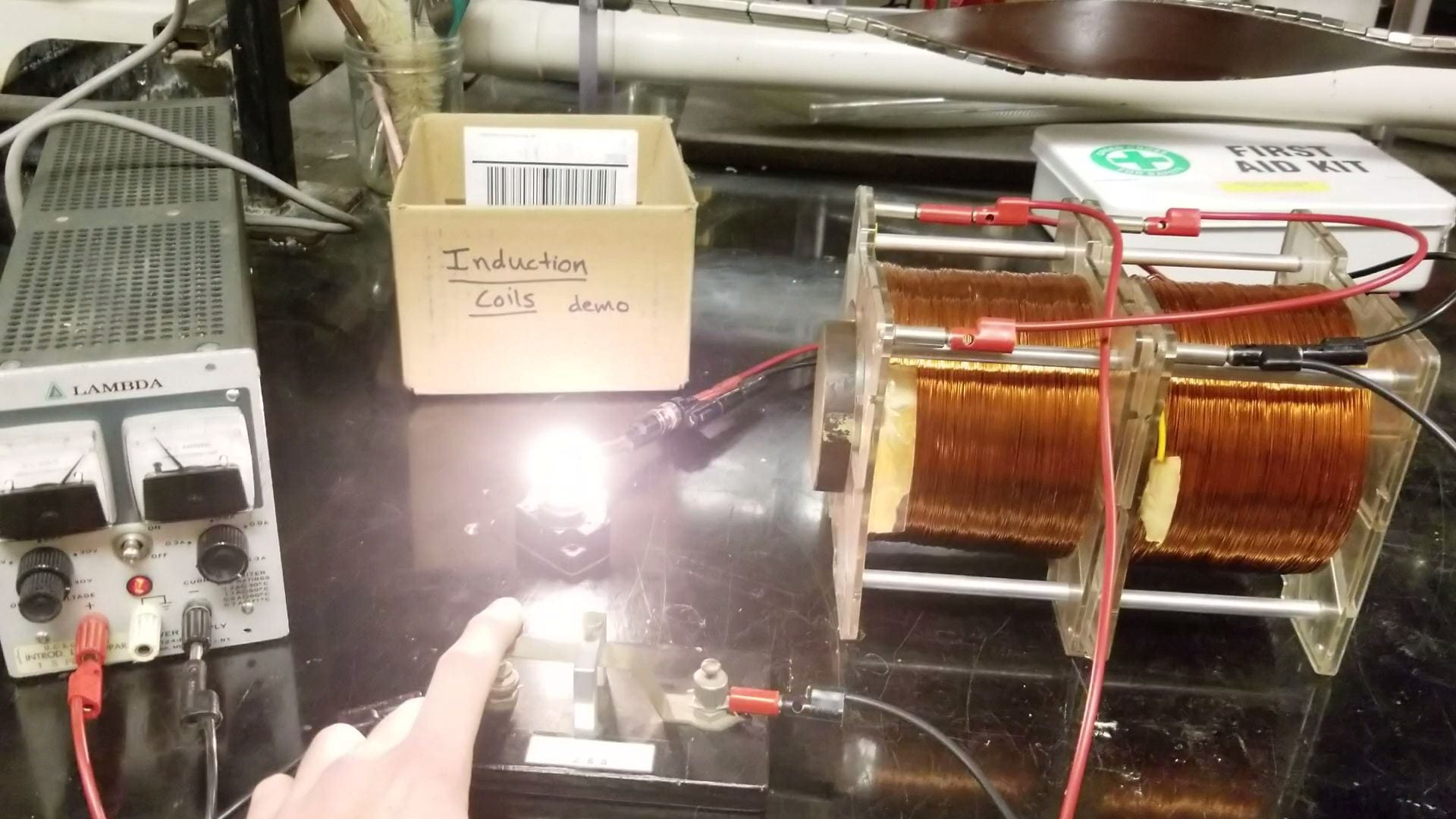
Figure 1: Magnetic field energy being converted to light
This demo shows that current flowing through a large inductor will build a magnetic field at its center. In addition, this magnetic field contains an energy which can be converted into electromagnetic radiation through the light bulb shown above in Figure 1. It is also possible to demonstrate mutual inductance between two inductors using the materials from this demo.
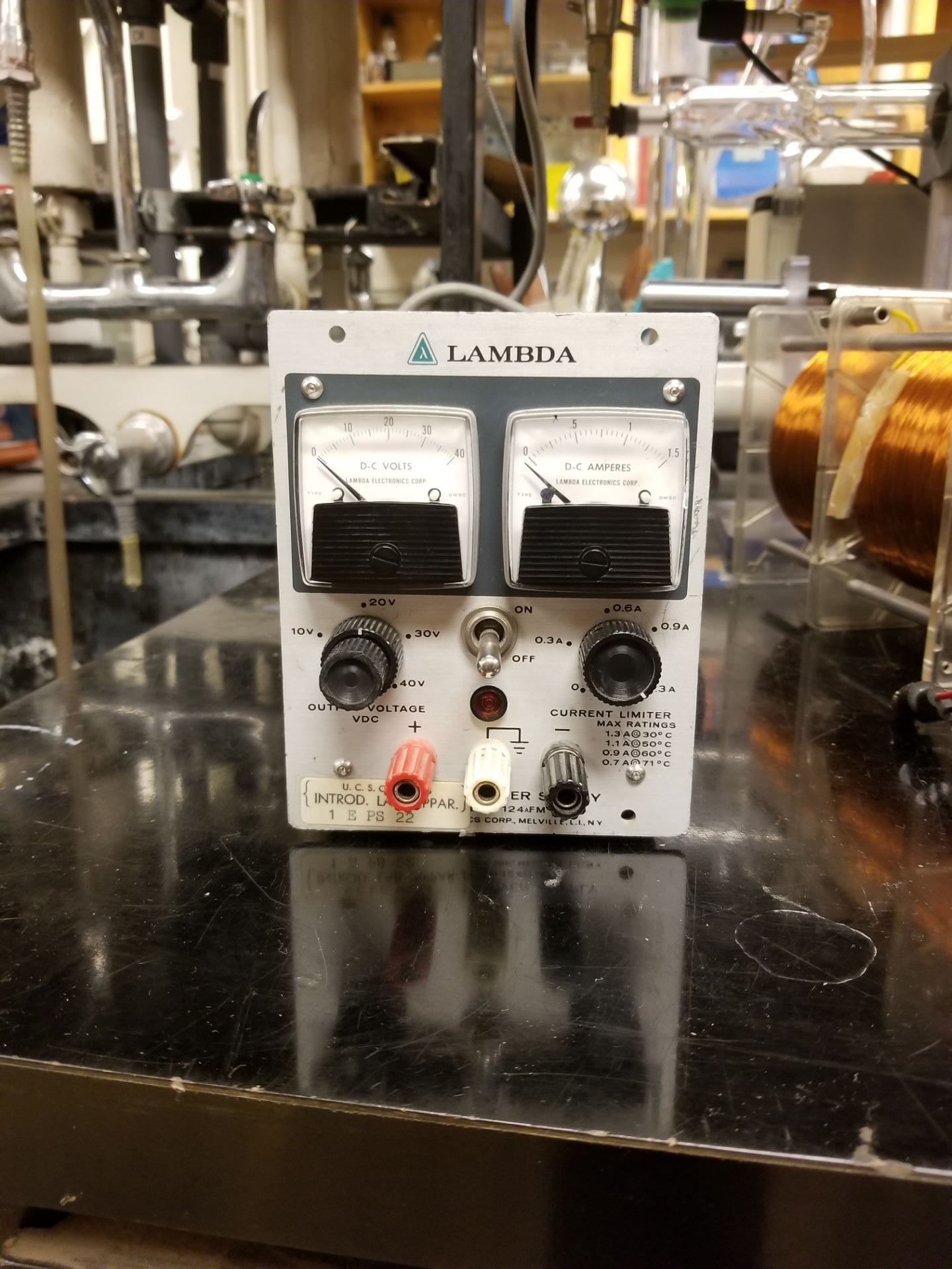
- DC power supply: The Lambda power supply is used to supply 40 V and up to 1.5 Amps to the system.

Figure 2: Lambda Power Supply (Metal Power Supply Cabinet)
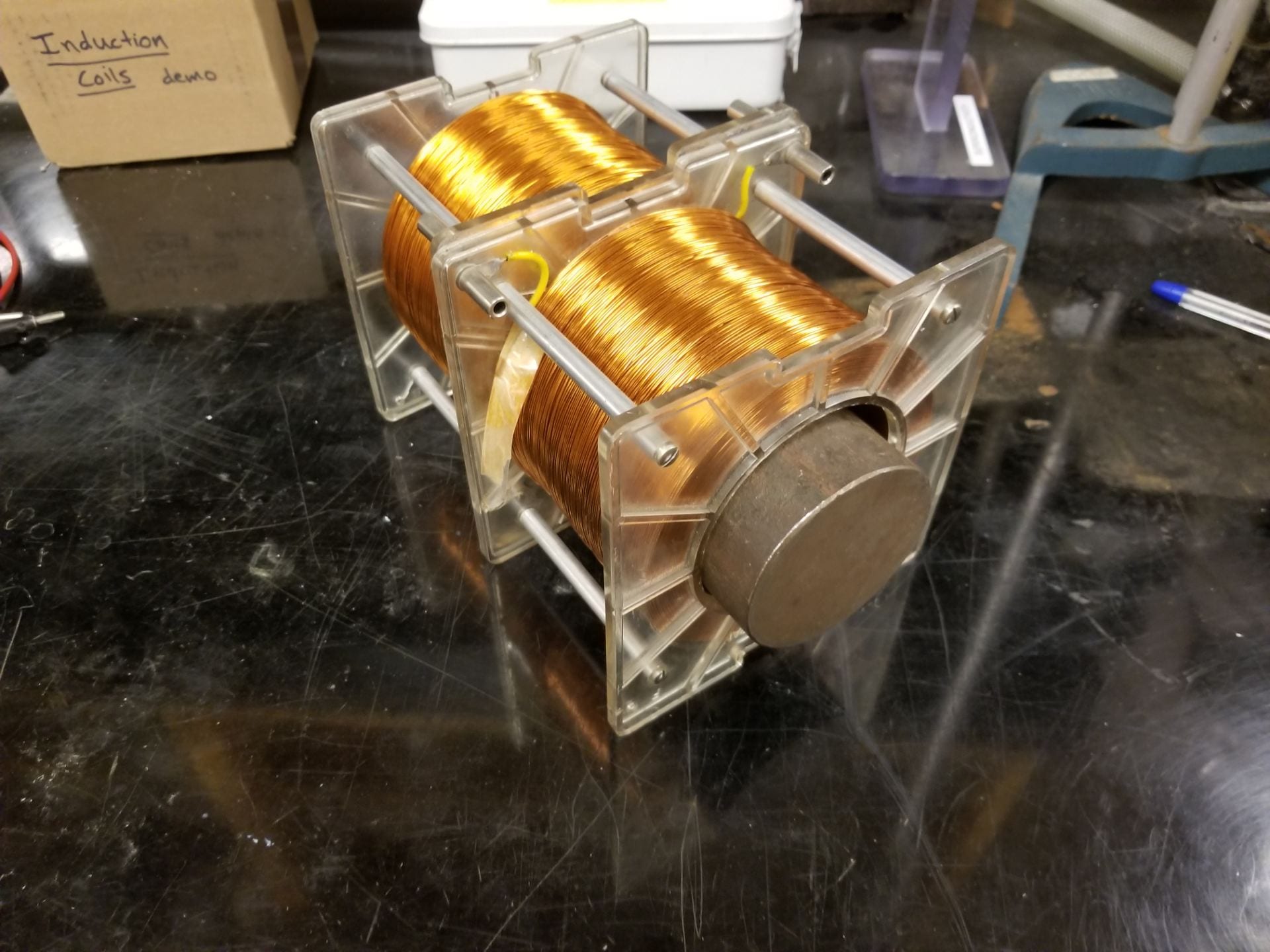
- Induction Coils and Core: For our inductor we use two large coils of 3400 turns each connected in series. In addition, an iron core is inserted to strengthen the central magnetic field created.

Figure 3: Induction Coils with Iron Core (Cabinet F4)
- Induction Coil Box: Contains a small light bulb rated for 120 V and 15 Watts and a momentary switch.
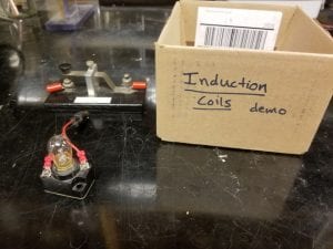
Figure 4: Induction Coil Box Contents (Cabinet F4)
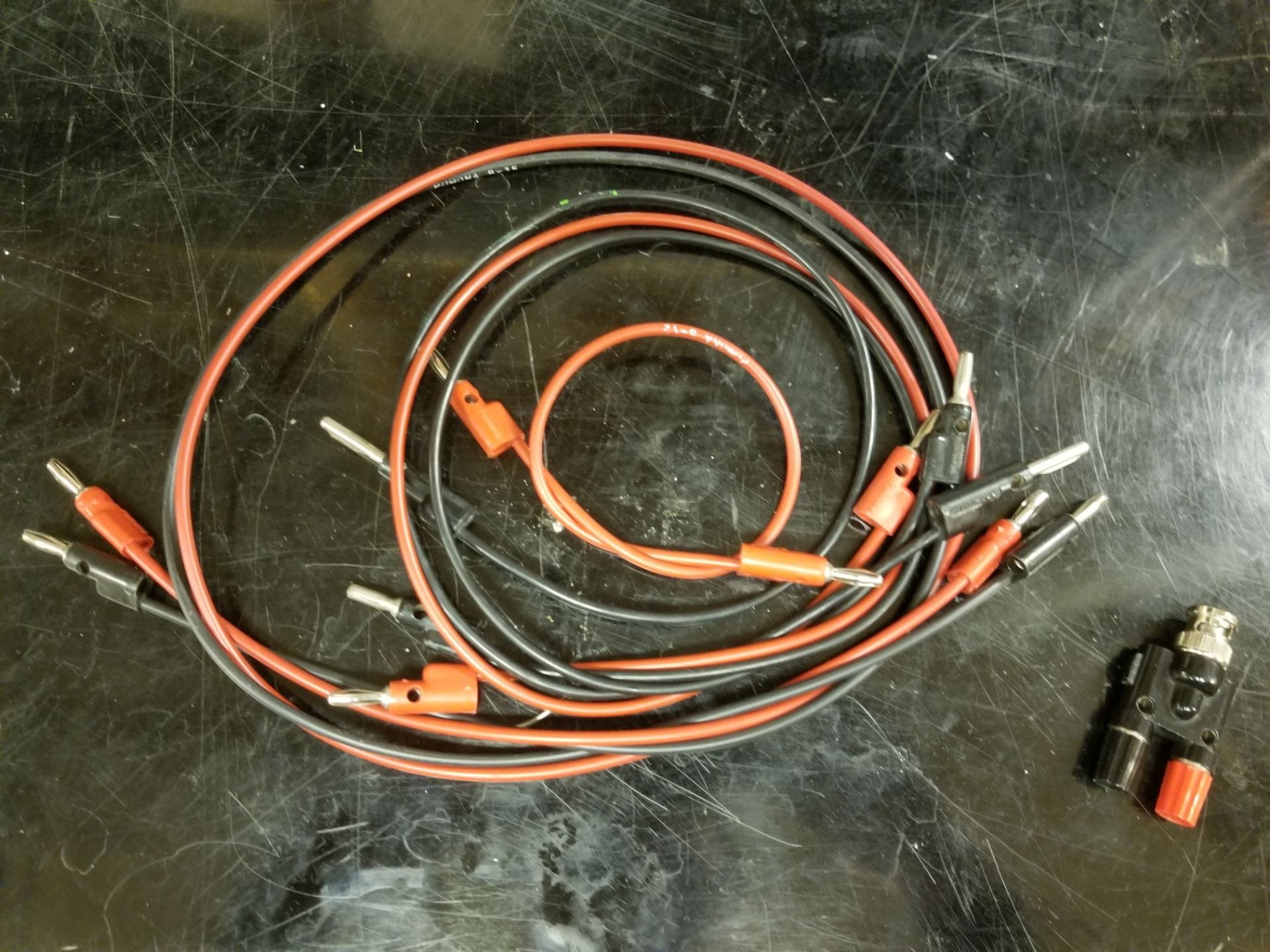
- Connectors: This demo needs 6 banana jacks and one BNC to banana jack connector as shown below.
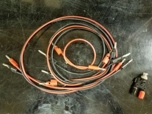
Figure 5: Connectors
- Video Camera: The camera helps students see small sparks between the momentary switch which might otherwise go unnoticed.

Setup:
To begin setup for this lab, assemble the circuit as shown below.

Figure 6: Setup Circuit Diagram
Connect the two induction coils in series with one banana cable. Then connect this combination in series with the Lambda power supply and momentary switch. This creates an open circuit when the momentary switch isn’t pressed down. Finally, connect the light bulb in parallel with the induction coils. This ensures that energy accumulated in the magnetic field within the iron core will be transferred to the light bulb until it is dissipated as heat and light. With the proper circuit assembled we can move to the demonstration itself.
Demonstration:
Without placing the iron core inside the coil, press the switch. The light bulb will shine dimly and turn off with no visible effect once the switch is released. Without the iron core the magnetic field is relatively weak and won’t generate a spike in light emitted when releasing the switch.
Now place the core inside the coil and press the switch again. Releasing the switch will produce a burst of light from the bulb and a spark between the contacts of the switch. It is best to perform this demo with the lights dimmed to observe this spark.
Explanation:
The two coils we’ve connected in series create one large inductor. Once current is steadily flowing through the inductor windings a magnetic field is created in the center. We will make use of the magnetic field within a solenoid with N turns per length and current I flowing to demonstrate this.

From this equation, we can see why current flowing through our inductor will create a magnetic field within its center.
Without an iron core this magnetic field is relative small due to the lack of material to magnetize. With the iron core inserted the magnetic field becomes much stronger. This is due to the large magnetization introduced by the iron atoms. Each iron atom is a strong magnetic dipole which is aligned by the external magnetic field, causing a net magnetization within the material. The effect is a much stronger magnetic field at the center of the inductor, which stores a much larger amount of energy.
Once the current stabilizes, visible on the Lambda source, we know that the magnetic field has reached its peak. Upon releasing the switch, we’ve disconnected the inductor from the power supply. The only remaining circuit is the inductor in series with the light bulb. At this point we need several electromagnetism equations to explain the following behavior.


In these equations we use 

When we begin to release the switch this will change our steady state current and magnetic field. Upon releasing it, we are effectively open circuiting, disconnecting, the power supply. This will stop current from flowing into the inductor as it had been while the switch was pressed in. However, this drastic decrease in current causes a large spike in 
Now that we’ve disconnected the power supply, the inductor and light bulb form their own isolated series circuit. Once the coils generate this electromotive force, the light bulb will also be affected by this voltage. With those steps, we’ve shown why the light bulb produces a bright flash when releasing the momentary switch. The spike in
One phenomenon still unaddressed is the source of power for this light bulb to shine. Because the inductor and light bulb are isolated, power must be supplied by the decrease of the magnetic field within the iron core. This power is delivered through the voltage generated by the inductor and the current this produces.

The power delivered to the light bulb surges as the supply is disconnected because the current is essentially a step function. The second it is removed,
The high voltage, or
One final effect we need to explain is the difference between reactions of the light bulb when the iron core is inserted and when it is removed. The important equation to note is
In this equation, the key relation is that
Written by Noah Peake