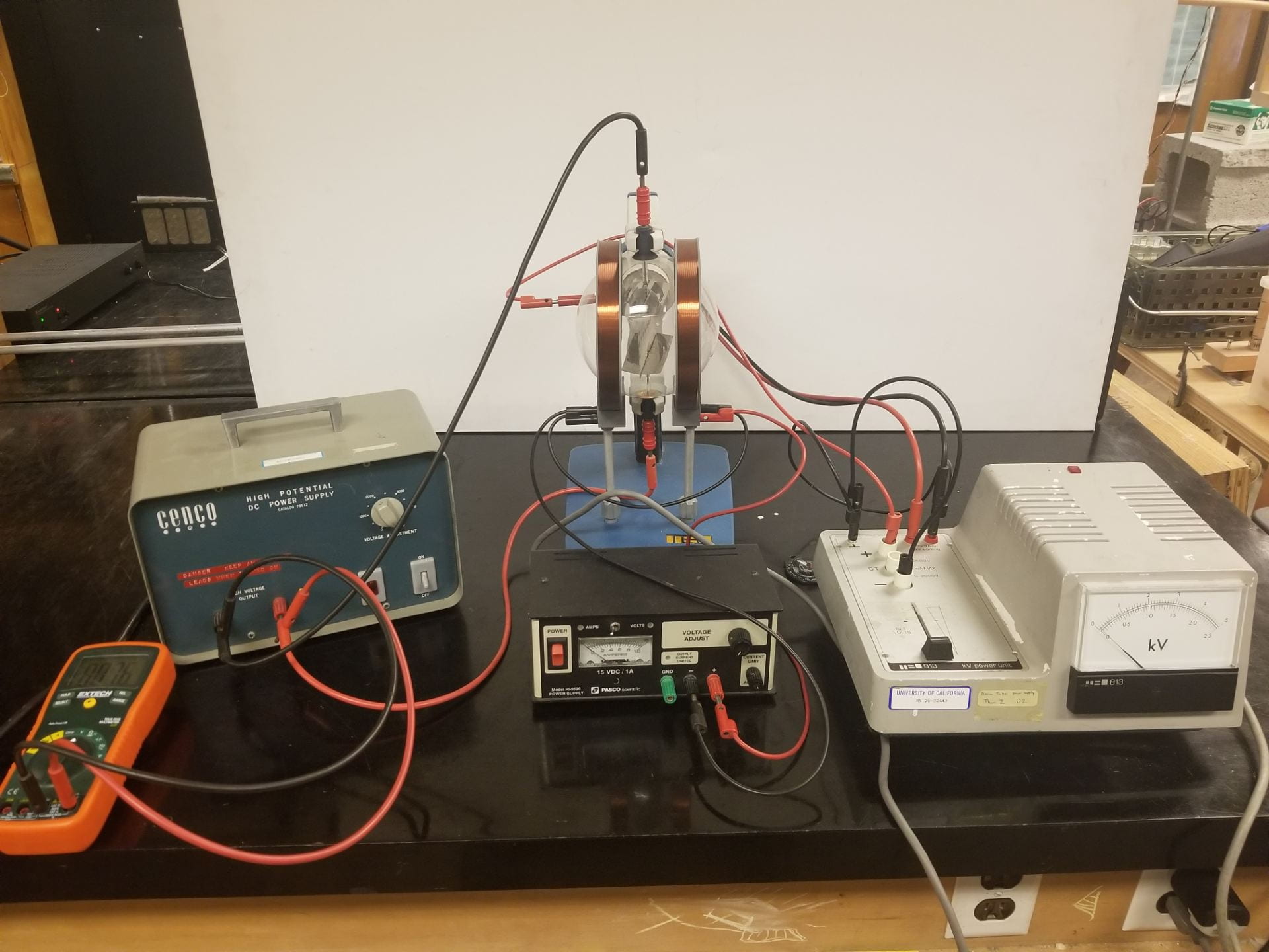
Figure 1: Electron velocity selector general setup
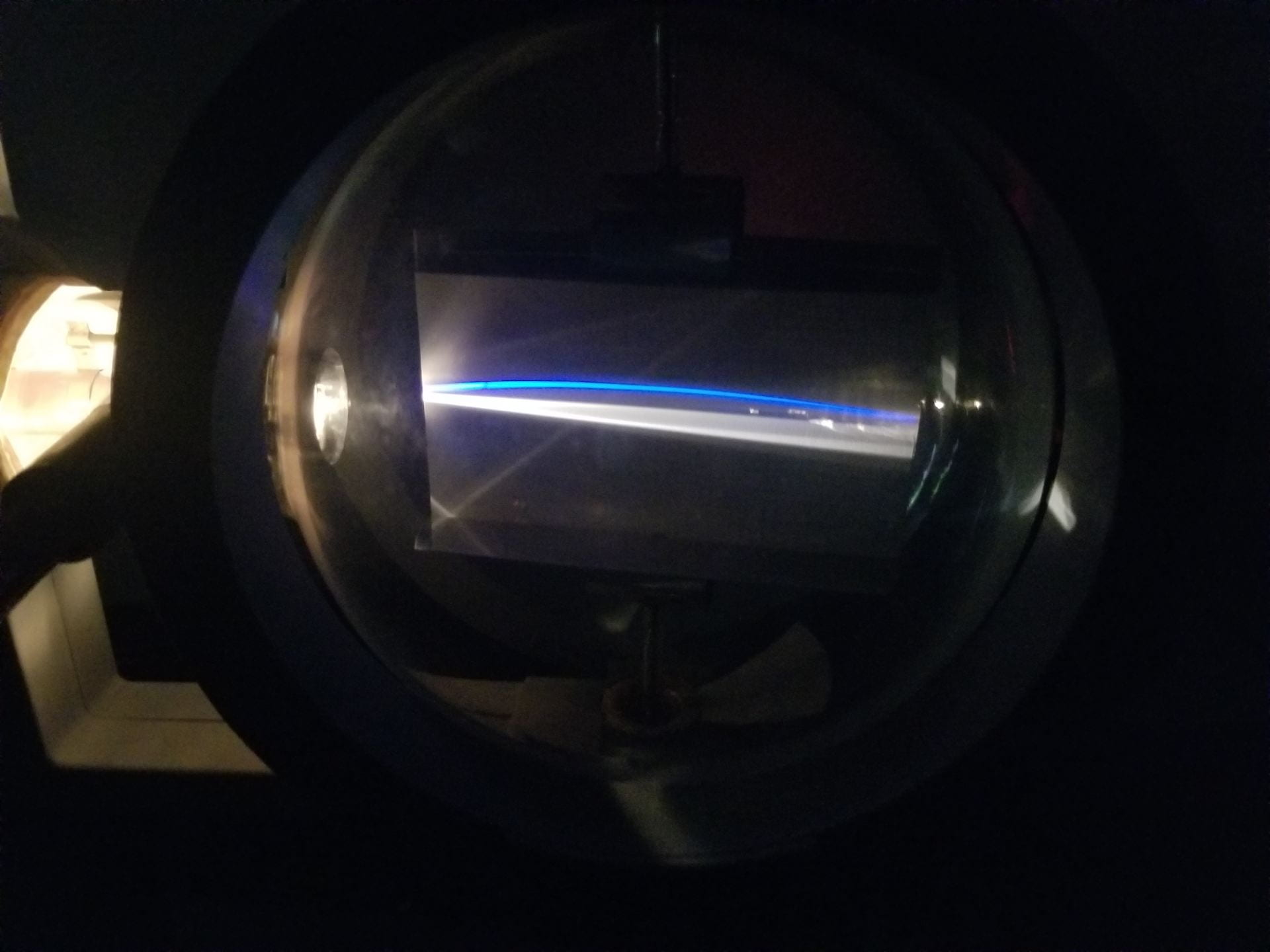
Figure 2: Electron beam deflected by both E and B fields
A vacuum tube with luminescent screen is used for both demonstrations. A glowing trace on the screen represents the path of the electron beam. The vacuum tube has terminals for applying high voltages to the cathode ray tube (3,000 V) and across the deflecting plates (500-600 V). The cathode of the tube is heated by 6.3 V (AC). Vacuum tube is secured on a special stand between 2 Helmholtz Coils that provide a uniform magnetic field across the space between deflecting plates. The setup is shown in Figure 1 while a demonstration of the beam is displayed in Figure 2.
Materials:
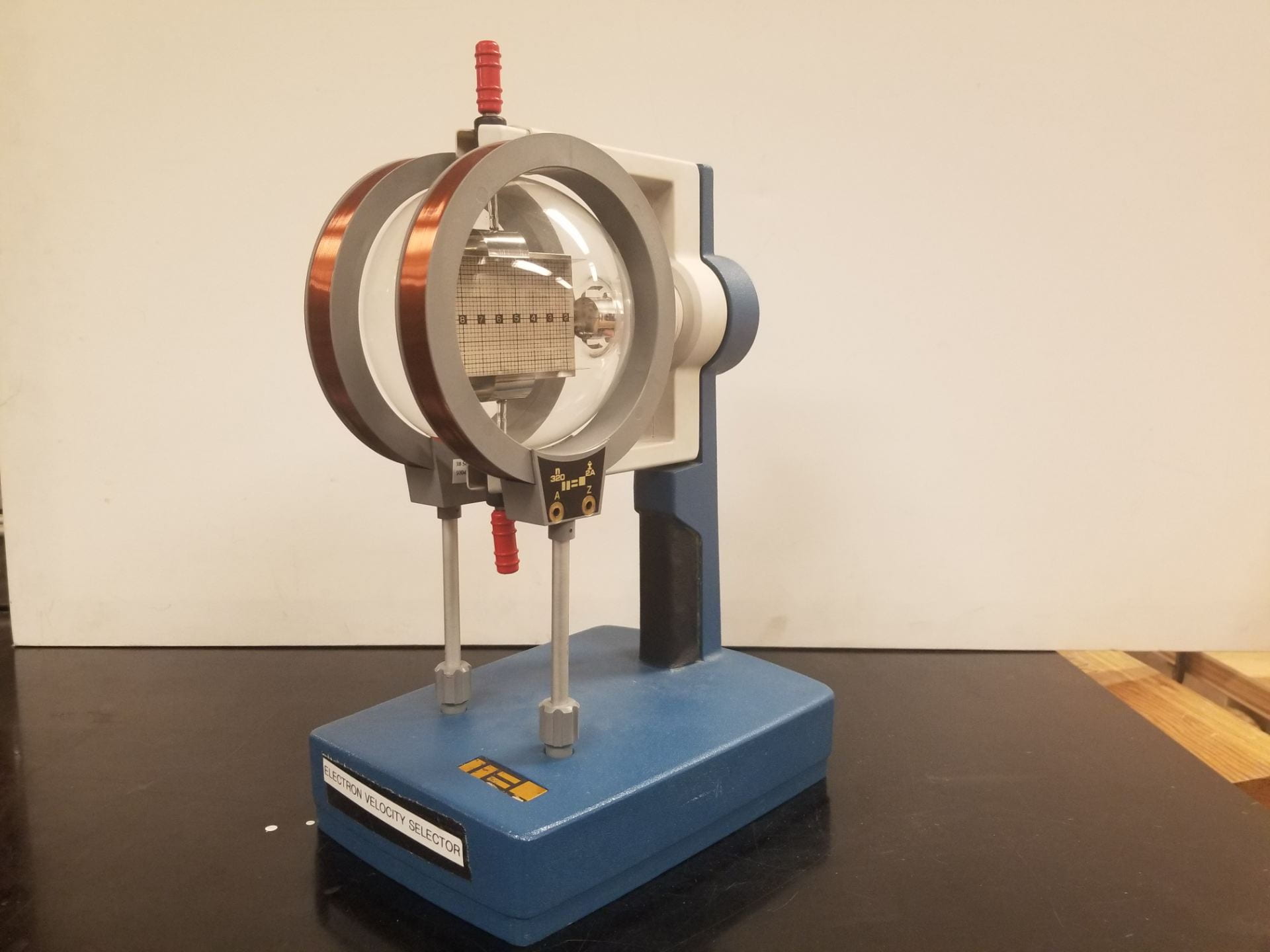
- Electron Velocity Selector – Device which produces a beam of electrons, apparatus shown in Figure 3. [Cabinet D2]
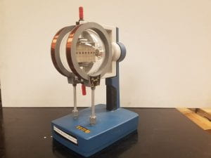
Figure 3: Electron velocity selector, 3B Scientific 50047
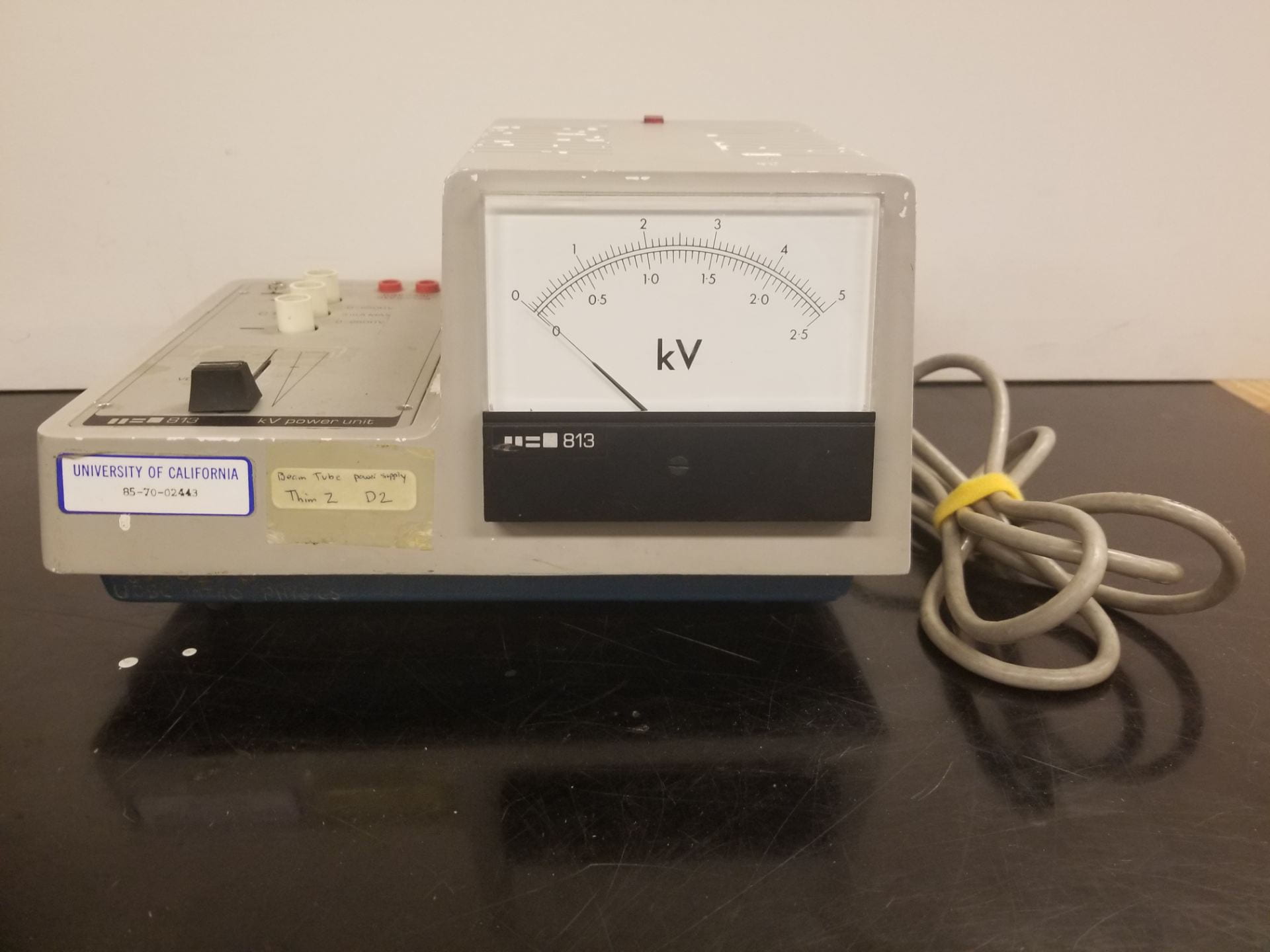
- Teltron Power Supply – Provides up to 4.5 kV to accelerate the electrons used in this demo, along with a smaller 6.3 V supply to heat the cathode of the cathode ray tube. A picture of this supply is provided below in Figure 4. [Cabinet K]
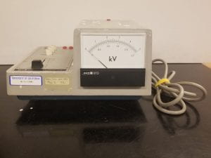
Figure 4: Teltron power supply, model 813
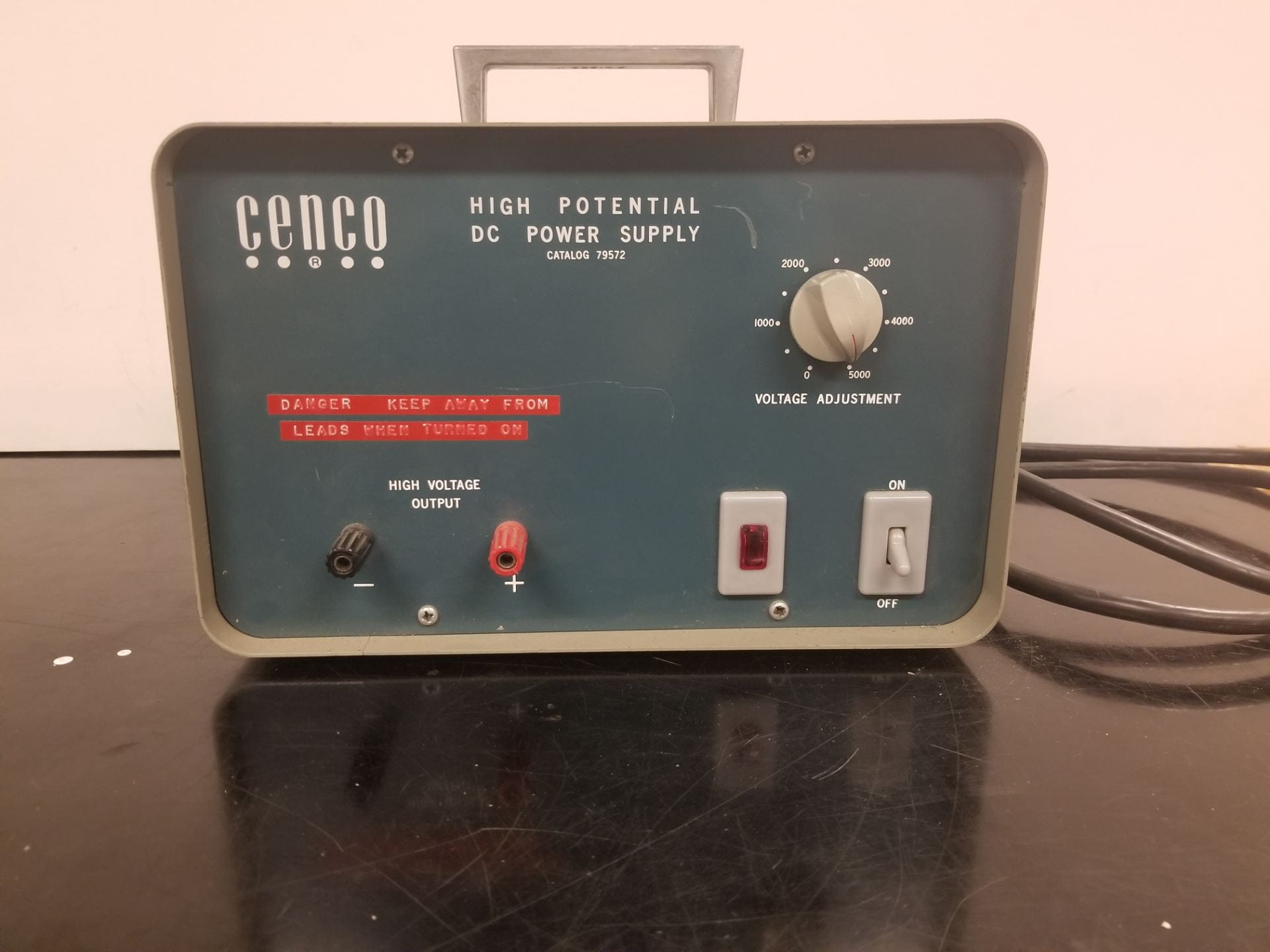
- Cenco Power Supply – This supply produces up to 5 kV to create a strong electric field between the plates within the vacuum tube, shown below in Figure 5. [Cabinet K]

Figure 5: Cenco power supply, model 79572
- Pasco Power Supply – This small 12 V supply drives current through the Helmholtz coils, displayed in Figure 6. [Cabinet K]
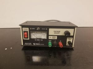
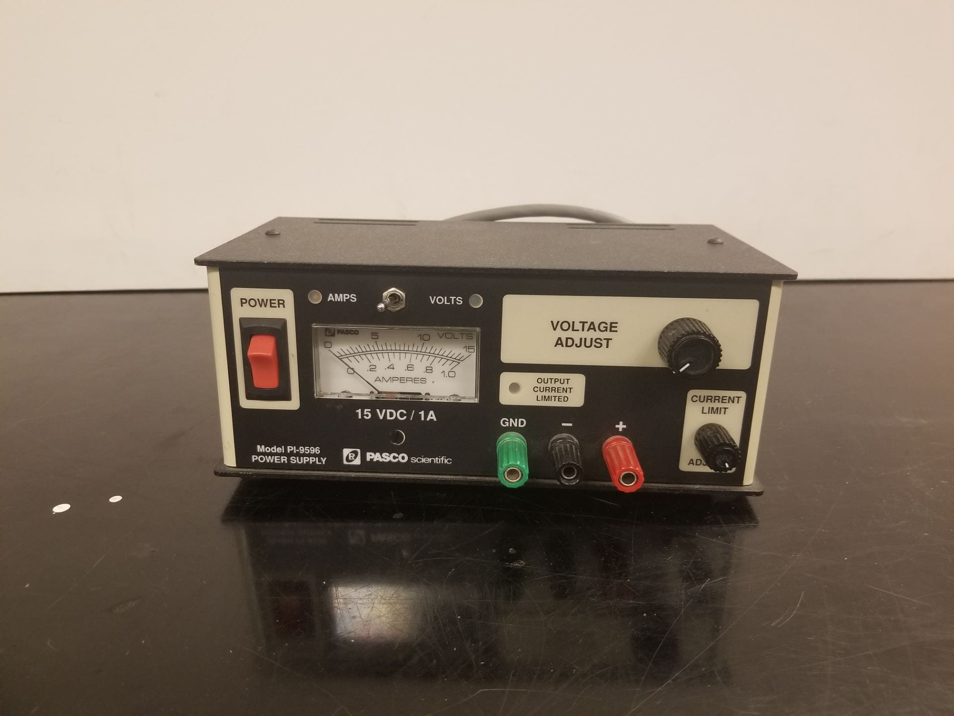
Figure 6: Pasco power supply, model Pl-9596
- Multimeter – Used for its voltmeter function to gauge the output of the Cenco power supply. [Below Cabinet J]
- Banana Jacks (12)
Setup:
To set up the electron velocity selector, all power supplies must be connected to the electron velocity selector according to the circuit diagram in Figure 8 below.
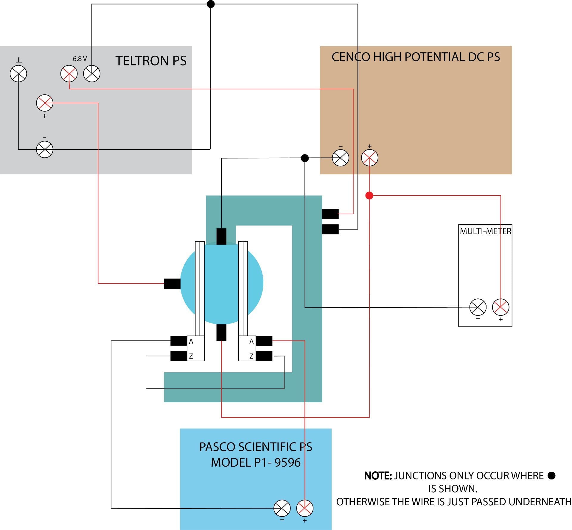
Figure 8: Setup diagram
In addition, the general setup is shown in Figure 1 up above for reference.
Part 1: Electron Velocity Selector
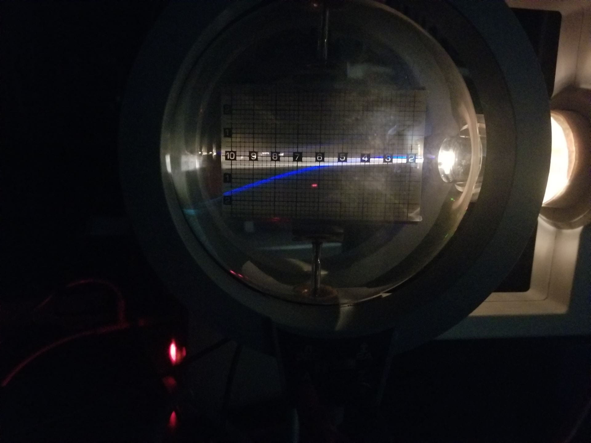
Figure 9: Electron beam in E field
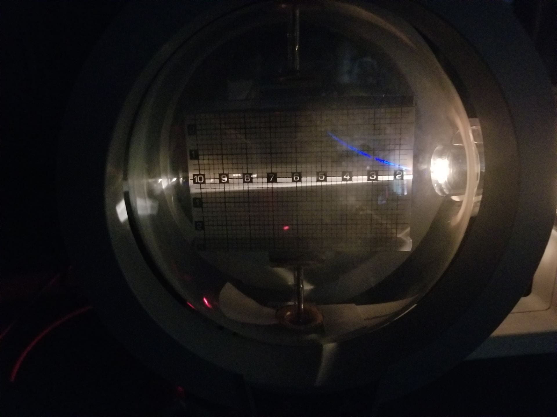
Figure 10: Electron beam in B field
Electron velocity selections are made by applying combinations of electric (E) and magnetic (M) fields perpendicular to the electrons’ path as well as to each other. Only electrons with velocity 
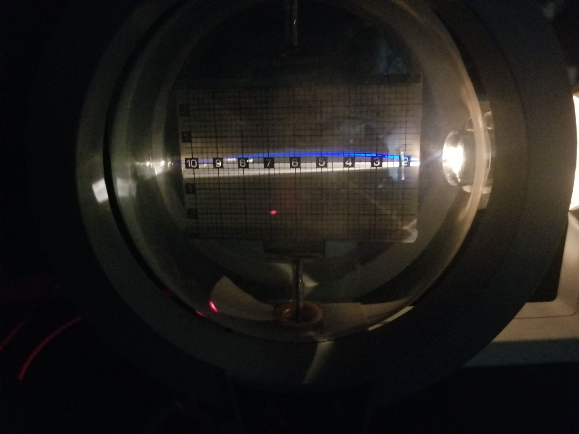
Figure 11: Electron beam straight path
Part 2: The e/m Ratio
In addition to the electron velocity obtained in part 1, further measurements are needed to calculate the e/m ratio.
The deflecting electric field (Cenco supply) should be switched off so that only the magnetic field remains. In a uniform magnetic field perpendicular to an electron beam, the trace on a fluorescent screen takes shape of a semicircle as seen in Figure 10. The radius of this circle is adjustable through the strength of the magnetic field, and can be used to calculate the e/m ratio with 
Notes:
- Demo best shown with dimmed lights
- Video camera recommended for large classes
Written by Noah Peake