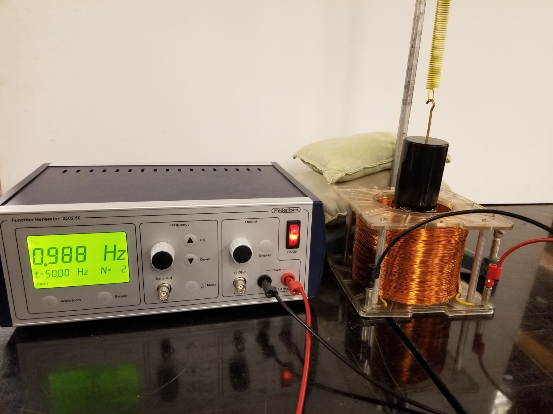
Figure 1: Driven EM Oscillator
The driven EM oscillator is a mass on a spring oscillator which is driven by electromagnetic forces. These forces are provided by magnets on the bottom of the mass, an induction coil surrounding the mass, and an AC voltage applied to the coil.
Materials:
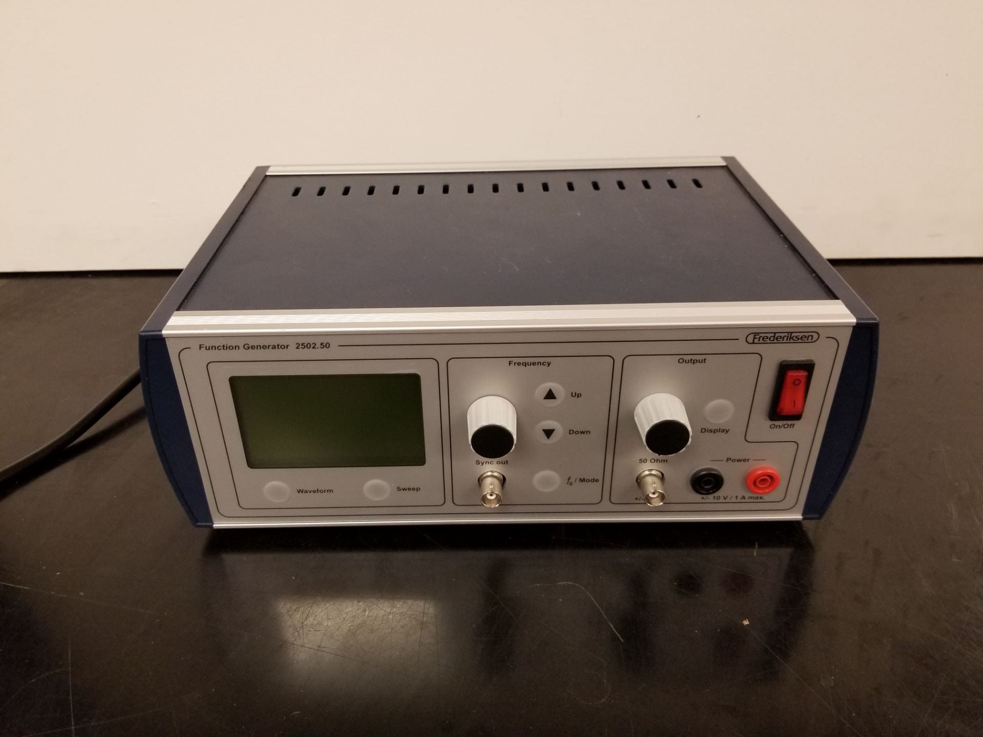
- Function generator — The Frederiksen function generator is shown below, but any generator with a finely adjustable frequency will do. [Cabinet K1]

Figure 2: Frederiksen function generator 2502.50
- Induction coils — Generates an alternating magnetic field which interacts with the mass and attached magnets. [Cabinet F4]
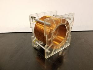
Figure 3: Induction coil
- Mass and magnets — Any iron mass will do, but the 1 kg mass below is preferred for its larger surface area for more magnet attachment. [Cabinet A3 and F3]
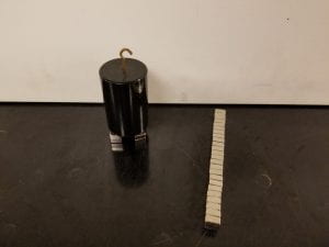
Figure 4: 1 kg mass and neodymium magnets
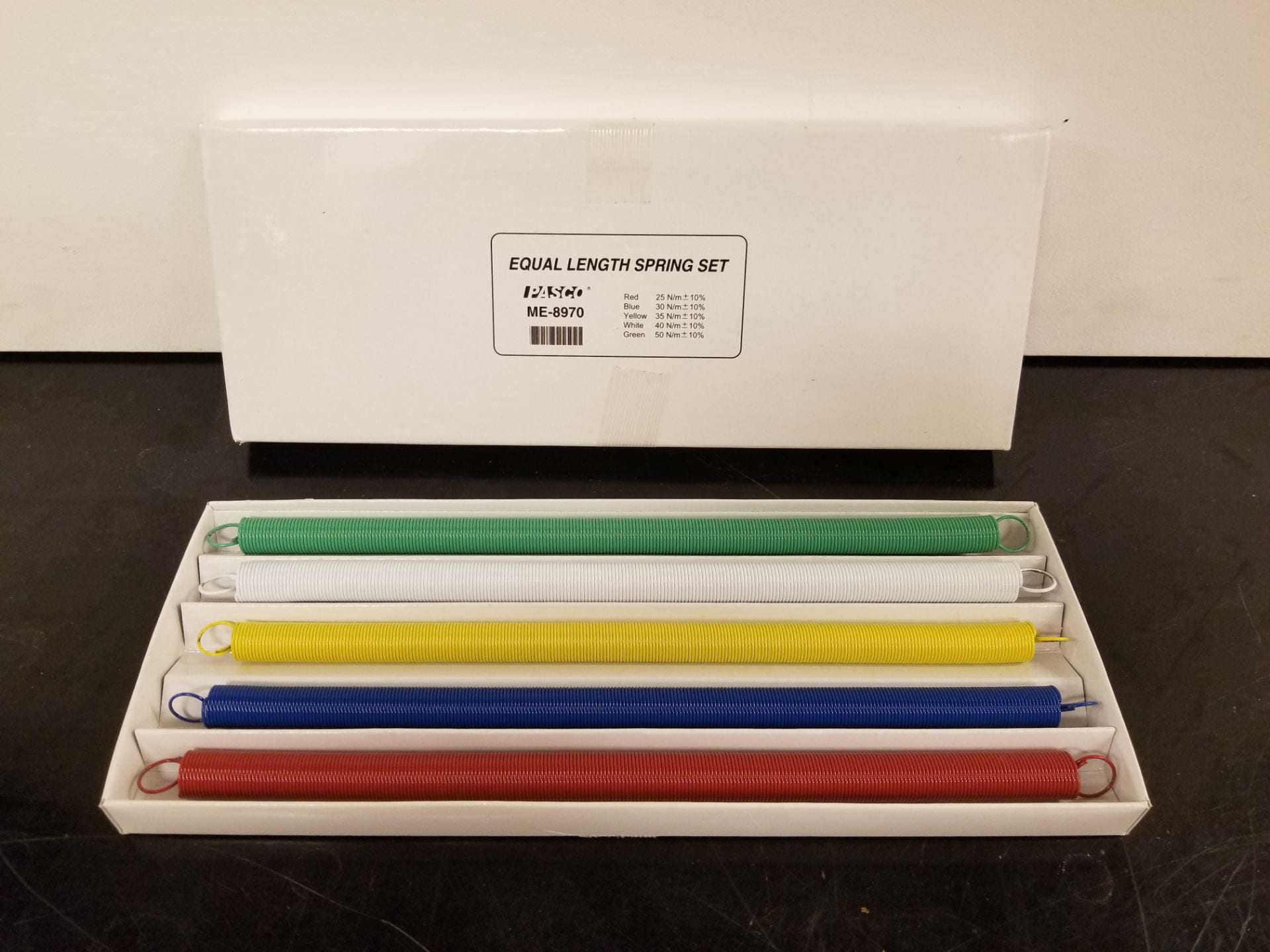
- Spring set — This set with varied spring constants allows for changing resonant frequencies of the oscillator system. [Cabinet C3]
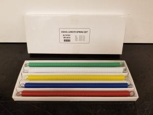
Figure 5: Spring set
- Stand assembly and sandbags — The rod and stand assembly is used to hold up the mass and spring oscillator, while the sandbags provide support for the stand. [Cabinet A3]
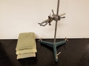
Figure 6: Rod and stand assembly with sandbags


Setup:
Assemble the equipment as shown in Figure 1 in the introduction. Off screen in this figure, the spring is looped around one of the small rubber arms of the clamp attached to the rod. The clamp height must then be adjusted so the bottom of the mass is flush with the induction coils, and the magnets extend below into the coil volume. This allows for the largest amplitude of driving force from the signal generator. Push the rubber clamp arms as close to the tall vertical rod as possible to increase stability. Rotate the clamp around the tall rod until it is centered over a gap between the tripod legs. This allows room for the induction coil to be placed as close to the base as possible. Finally, use two banana jacks to connect the signal generator to the induction coils. Polarity isn’t important because the incoming signal is AC.
Demo:
Turn on the function generator and set the frequency to around 1 Hz. The resonant frequency is different for each spring, but each is on the order of 1 Hz. Turn up the amplitude one quarter turn and slowly adjust the frequency according to the table below. Once the mass reaches the maximum displacement it is being driven at the resonant frequency. This resonant frequency can be changed using the different springs provided.
| k (N/m) | f0 (Hz) | |
| red | 25 | 0.752 |
| blue | 30 | 0.83 |
| yellow | 35 | 0.895 |
| white | 40 | 0.96 |
| green | 50 | 1.07 |
Table 1: Spring constants and resonant frequencies for each spring in the set, assuming the 1 kg mass is used
There are several other phenomenon worth showing to students. First, that the mass and spring system oscillate freely as expected when the banana jacks to the inductor are removed, or the power supply is off. Next, the function generator can either drive or damp the oscillator depending on the input voltage. With the mass at rest, turning up the amplitude will begin oscillations if the frequency is near resonant. However, if the function generator is on with the amplitude decreased to zero, it will actively dampen the oscillator and bring it to rest.
Explanation:
The basis for this demo depends on the mechanics of the simple harmonic oscillator formed by the spring and hanging mass. For a quick review, this system has two forces acting on it, Hooke’s law for springs 


where 
By making several modifications to the mass on a spring setup we can create a driven oscillator. First, magnets are added to the bottom of the iron hanging mass to fix a magnetic field around the oscillator. Then, the induction coil is placed such that the mass will pass in and out of its enclosed volume. This couples the oscillating mass with the stationary coil. Finally, an AC signal is applied to the coils using the function generator. The alternating current sent through the coil then induces an alternating magnetic field within the volume of this coil. The induced magnetic field alternates between attracting the mass into the coil and repelling the mass upwards. Through this mechanism the simple harmonic oscillator is converted into a driven oscillator using electromagnetic forces.
The frequency and amplitude of the EM driving force is finely adjustable using the function generator. As discussed above, the hanging mass oscillator has a frequency of oscillation determined by the spring constant and mass used. When the system is driven, this frequency becomes known as the resonant frequency. As the driving frequency approaches the resonant frequency, the amplitude approaches its maximum.
A useful example of driving at the resonant frequency can be seen when swinging on a swingset. As a child, one learns to swing their legs at the same frequency at which the swingset naturally wants to swing at, the resonant frequency. The use of one’s legs to get higher is the driving force. Swinging one’s legs off the resonant frequency is ineffective, but swinging at the resonant frequency allows the swinger to reach the maximum amplitude.
The swingset example relates to the driven EM oscillator case as follows. The resonant frequency that the swingset prefers to oscillate at translates to the hanging mass simple harmonic oscillator’s resonant frequency determined by mass and spring constant. Then the act of swinging one’s legs to get higher is analogous to the function generator providing the driving force of an alternating current within the induction coil. As in the swingset case, maximum amplitude for the oscillating mass will be achieved when the driving frequency matches the resonant frequency of the non-driven system.
Written by Noah Peake