Description:
Heron’s fountain is a hydraulic machine that demonstrates the principles of hydraulics and pneumatics. Flow of water from high gravitational potential energy to low gravitational potential energy causes a fountain to form, due to increasing pressure on the inside of the system.
Materials:
- Two large jars with lids and basin
- 3 tubes to connect jars and basin together
- clamp
- Large volume of water and coffee containers to pour
- Towels
Demo:
The stepladder is a good frame for the Heron’s fountain demo as it allows you to change the relative heights of the containers to change the fountain effect. To start the demo container 1 must be empty, container 3 should have water up to the bottom of the straw, and container 2 should be completely filled with water.
There are three tube which be connected to the small glass straws sticking out of the lids of the jars. One tube must be going from the bottom of container 1 to the bottom of container 3, one from the top of container 3 to the top of container 2, and one from the bottom of container 2 through the floor of container 1 to form the fountain.
The tube leading from container 1 to container 3 should be primed before the demo is started. To do this you want to fill the tube with water (using a vacuum, siphon, etc.) and use the clamp to hold it closed while you connect it to the glass straw stemming from container 1. If this tube is not primed prior to use, the fountain will not work well. Priming the tube creates a large column of water quickly that would otherwise take time to form. The height of this column of water is what drives the fountain, as is discussed more in depth later.
Notes:
- A bigger effect will be seen when the distance between 1 and 3 vertically is the greatest. The length of the tube is not important for the pressure calculations, only the vertical height is important. Because of this, in order to change the size of the fountain you need to raise or lower the containers: Simply putting in a longer tube will not change the height of the fountain.
Explanation:
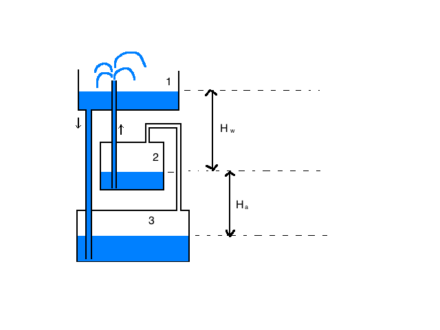
As it is labelled in the preceding image, assume the top basin is container 1, the middle basin is container 2 and the bottom basin is container 3. The system has an effective height of 


To start the fountain, container 1 should be open to the air and holding no water. Container 2 should be filled to the top with water, container 3 should be filled with water to the bottom of the straw, and the tube from container 1 to 3 must be primed. To begin the fountain, pour water into container 1 until it is filled. Almost immediately you should see water spring up out of one of the holes in the top container.
Container 3 needs to have water filled up to the bottom of the straw because otherwise air can get into the straw and flow backwards into container 1, which impedes the flow of the water. Additionally, when bubbles of air exit this way, the pressure of the system is being released in the wrong direction. In order to drive the fountain we need high air pressure in container 3 which pushes the water down in container 2. If the air, instead of flowing into container 2 flows back up into container 1, the fountain will run slowly.
As water is poured into container 1, gravity pulls it down into container 3. The air filling container 3 is displaced by the denser water flowing down from the top, and rises up through the tube connecting container 3 to container 2. This air increases the pressure in container 2, which displaces the water that was previously occupying space. Because the pressure in container 2 is greater than atmospheric pressure, water will flow up the tube and form a fountain. The flow of water will stop once container 2 is empty of water.
This is not a perpetual motion device, although it may look like one. Eventually, all of the water in container 1 will drain to container 3, and there will be no longer be the pressure that was exerted on the system, driven by gravitational potential energy acting on container 1. While container 3 completely fills with water, container 2 loses all its water through the fountain and will fill with air. Once the level of the water in container 2 is below the level of the tube that connects container 2 to container 1, the fountain will stop. If you continue to pour water into the first container, the water level will rise up through container 3 and 2, following Pascal’s theory of communicating vessels. Communicating vessels are discussed more in depth here, on the page for our equilibrium tubes demonstration.
To increase the height of the fountain, you want to minimize 
To see why increasing g")
")


Because the pressure is related to the height of a column of fluid, the tube leading from container 1 to container 3 needs to be completely filled with water for the fountain to run well. If there is a slow trickle of water out of the top container into container 3, even though there may be a large vertical distance, the fountain will not work well because there is not a continuous column of water that adds to the pressure of the system.
In addition to changing the heights of the columns, you can change the height of the fountain and the running time by changing the diameter of the tubes used for the fountain on the right side. A smaller diameter tube will mean a higher fountain and a longer run time; a larger diameter tube will lead to a shorter fountain and shorter run time. The containers are air tight, so there must be equal flow of water into the system as out of the system. If you put a small opening for the fountain, the water flow out of that will dictate the flow rate of the whole system, and there will be a large buildup of pressure in container 2 because water does not escape quickly. As the diameter of the fountain gets smaller, the pressure in container 2 will increase, which will push the water out at a higher velocity, increasing fountain height.
This demonstration can also be thought of as a siphon with the upper arch of the tube missing. In this example, the positive pressure of the bottom two containers is what drives the water to move. In a “typical” siphon, it is generally agreed that the force that pulls the water up through it is a negative pressure at the top of the bend. There is a more in-depth explanations of how siphons work here at the page discussing the Pythagorean Cup demonstration.
Possible variations or changes:
Change out tubes leading from container 3 to container 2 and container 2 to container 1 to show how the run time and fountain height changes with tube diameter (fountain should stay the same, run time should go down with increasing diameter.
Partially blocking or not priming the tube from container 1 to 3 so that only a small trickle of water can come out. Have the class explain why the fountain works best when the flow of water isn’t impeded in any way and when there is a tall column of water.
Written by: Sophia Sholtz