
Figure 1: Diffracted spectrum using flash light and large grating
This demo showcases a brilliant full spectrum diffraction, or linear rainbow, which is projected onto a large screen.
Materials:
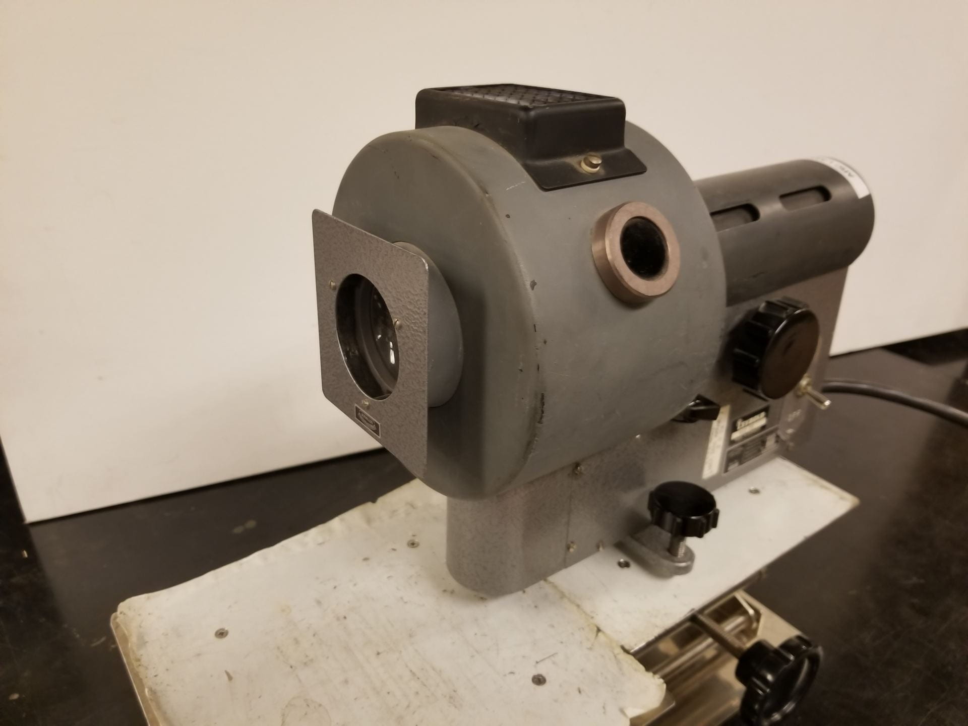
- Carbon Arc Lamp – This is our most intense light source, producing a concentrated beam of light by using electricity arcing between two rods of carbon. Shown below in Figure 2. [In cupboard between speakers and rod stands]
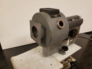
Figure 2: Carbon Arc Lamp and Jacks
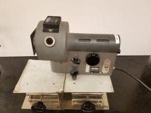
Figure 3: Carbon Arc Lamp and Jacks second angle
- Jacks – The jacks are used as a platform for the arc lamp to adjust its height off the table. To prevent the arc lamp from falling forwards and getting damaged, two jacks should be used back to back. These can be seen below the arc lamp in Figure 3 above.
- Flashlights – Less intense light sources which are more portable and easily adjusted and aimed, shown below in Figure 4. [Cabinet H3]
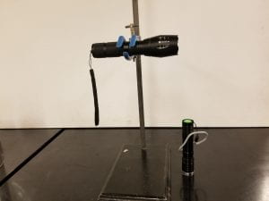
Figure 4: Flashlights and equipment to hold them
- Rods, Clamps, and Stands – These are used to hold the flashlight in place and can be seen above holding the flashlight in Figure 4. A tall stand for both flashlight and diffraction grating are required for larger classrooms. One of these large stands holding a diffraction grating can be seen below in Figure 5.
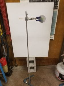
Figure 5: Tall Diffraction Grating holder stand
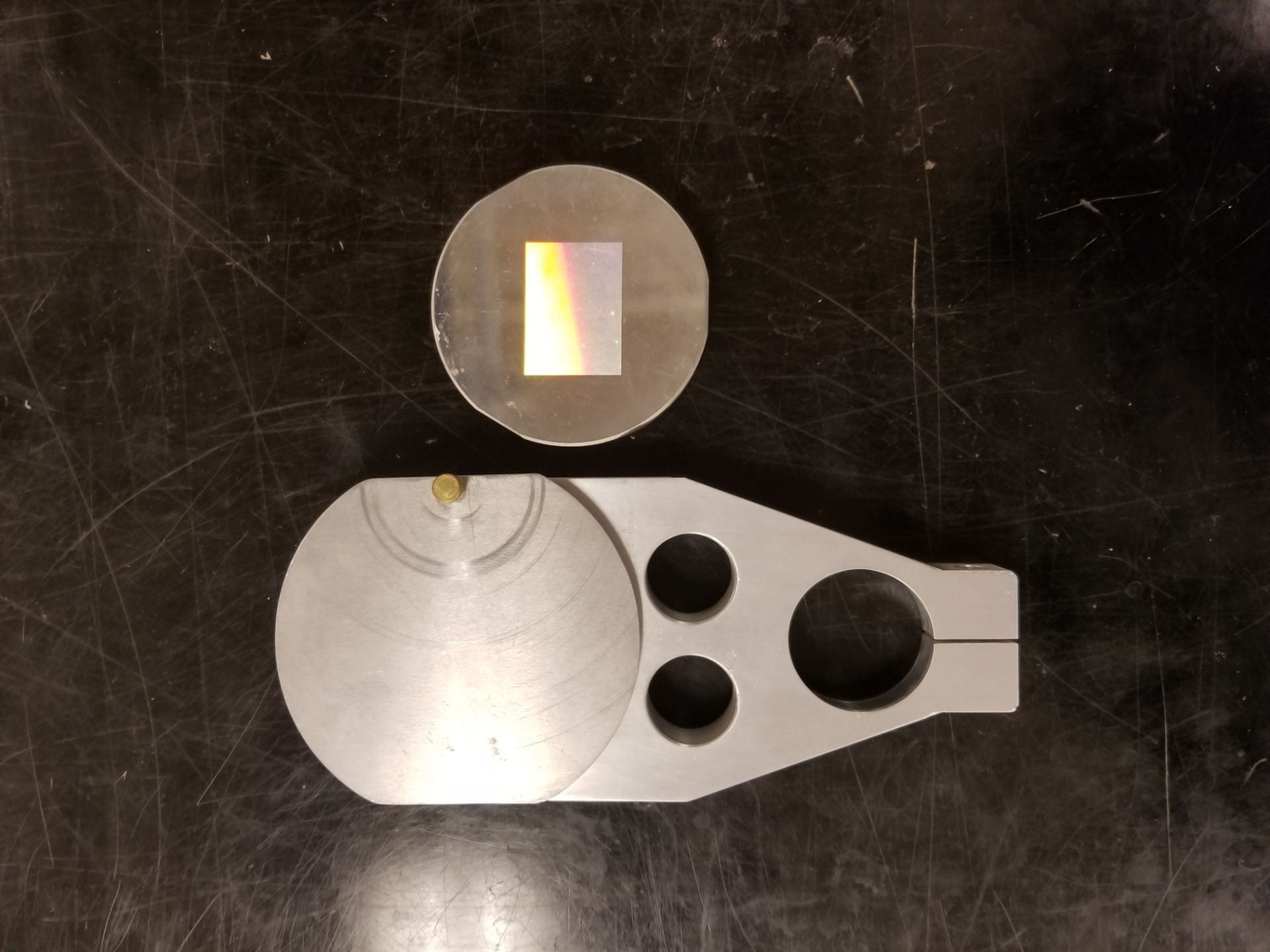
- Diffraction Gratings – These gratings work using reflection of light rather than transmission as with usual single or double slit experiments. The included gratings have different ridge spacing which produces spectra of different widths. The gratings themselves can be seen below in Figure 5. [Larger grating in cabinet E3, smaller found in E4 in a box labeled Cornell diffraction gratings]

Figure 5: Diffraction Gratings (1600 lines/mm for large grating)

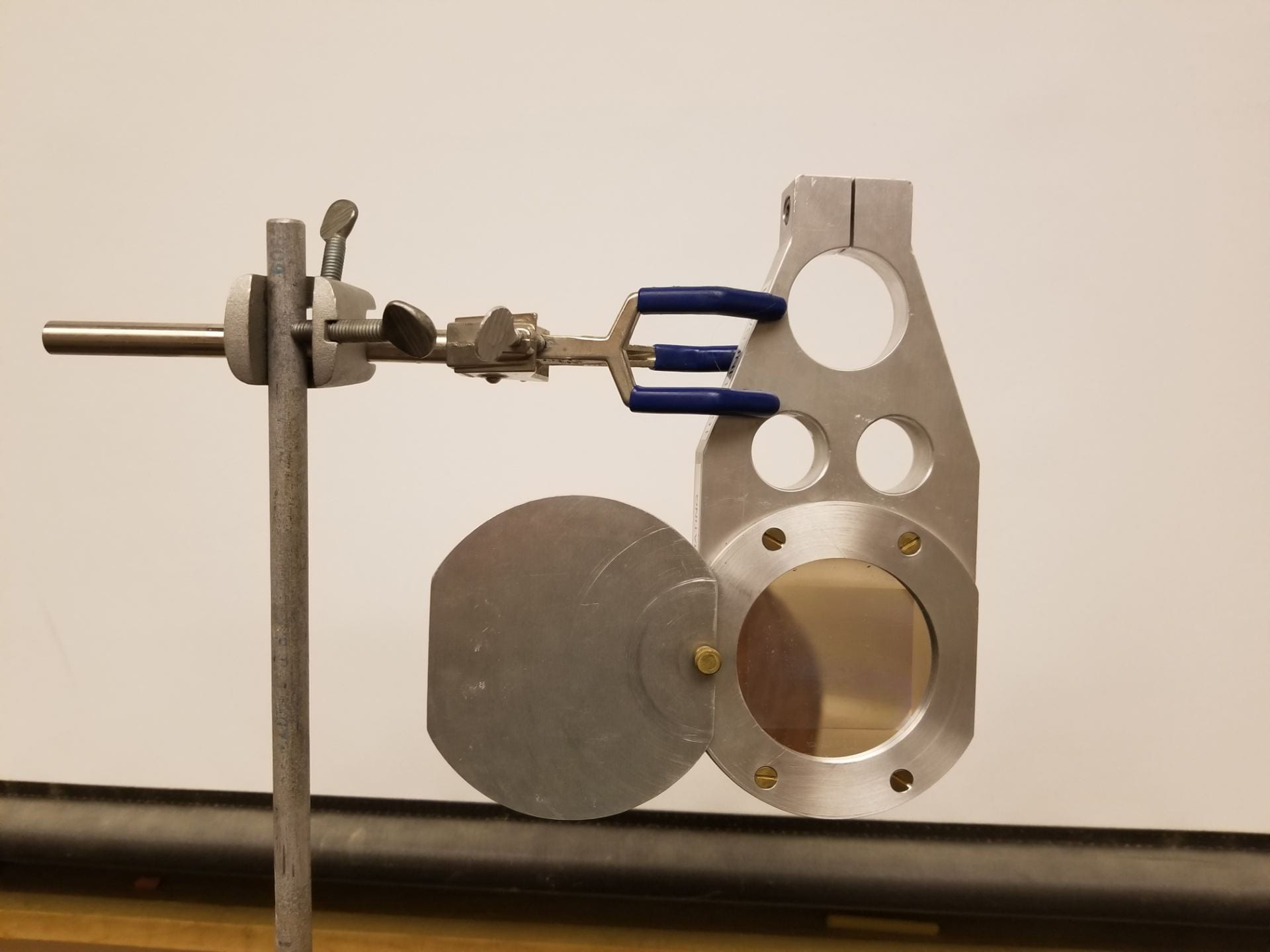
Figure 6: Proper clamping of larger grating to tall stand

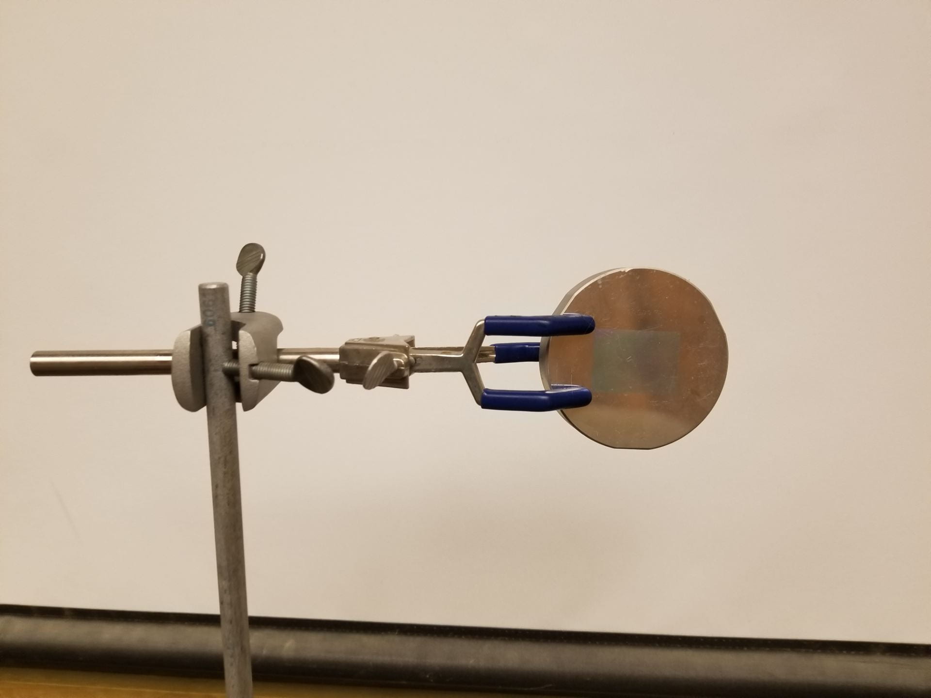
Figure 7: Proper clamping of smaller grating to tall stand


Setup:
To set up this demo, light from one of the sources must strike one of the gratings and be reflected back towards the light source onto a large screen. This basic concept is shown below in Figure 8, as performed in the demo room.
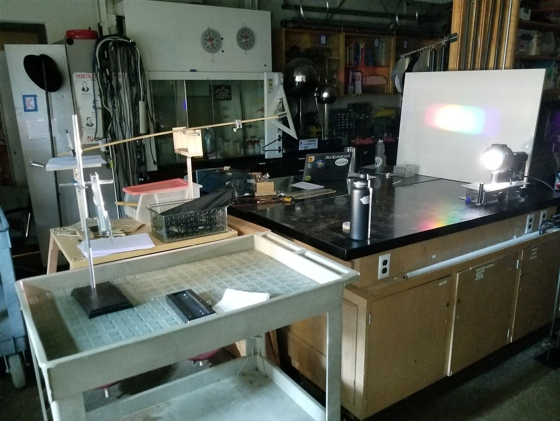
Figure 8: Demo room linear rainbow setup
Using this setup, several spectra can be produced corresponding to different light source and diffraction grating combinations. These are included below in Figure 7, Figure 10, and Figure 11 properly labeled by their light source and grating used to create them.
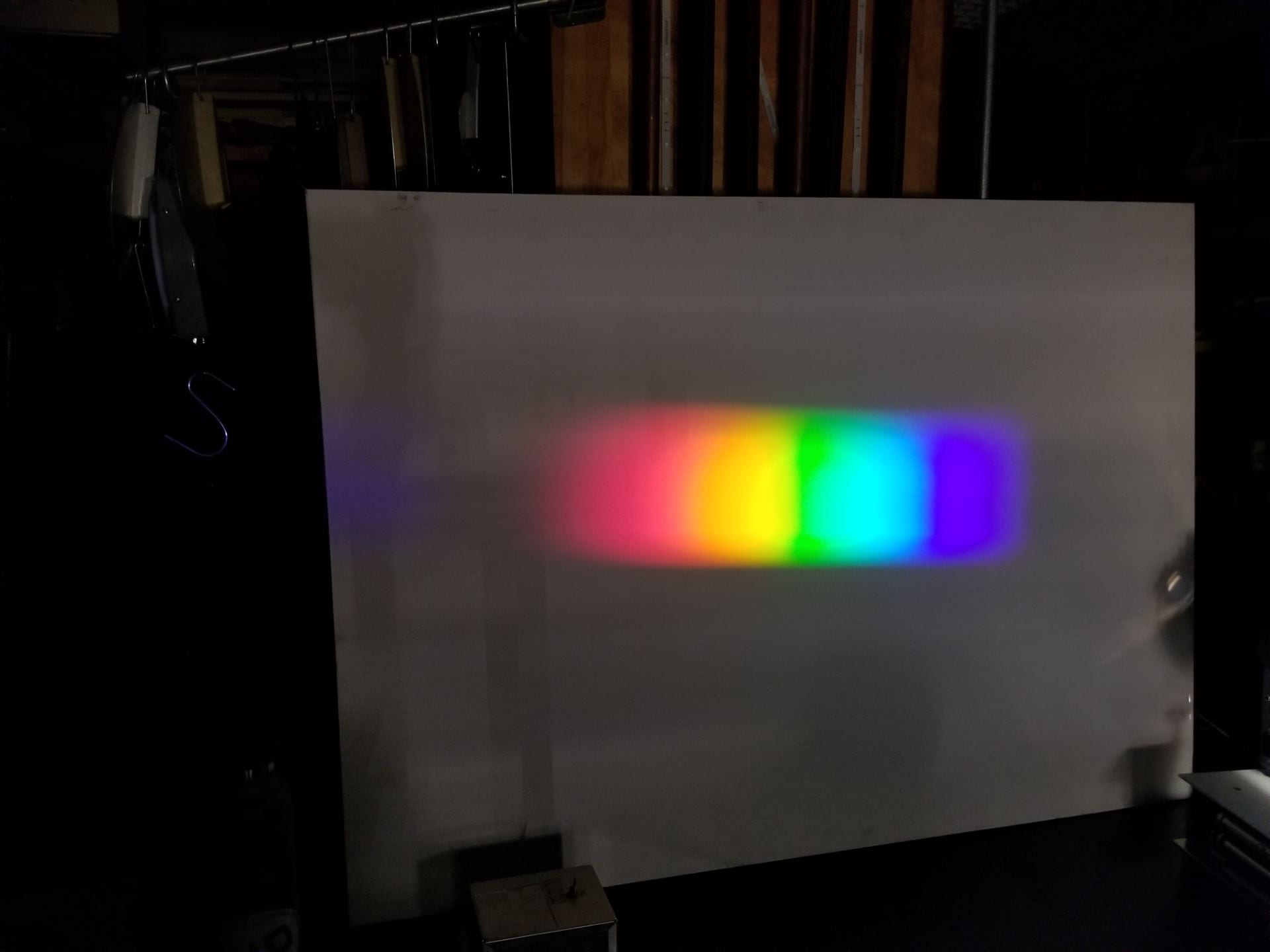
Figure 9: Spectra from arc lamp and larger grating
Using the carbon arc lamp as a light source produces a more intense spectra. This source will be useful in classrooms that can’t be made completely dark, or when trying to produce the largest spectrum possible.
Figure 10: Spectra using flashlight and large grating
With the flashlight as a light source, the spectrum is more difficult to see as the flashlight doesn’t emit as high intensity of light as the arc lamp. This source is useful for its portability, ease of use, and ability to finely tune the light’s angle.
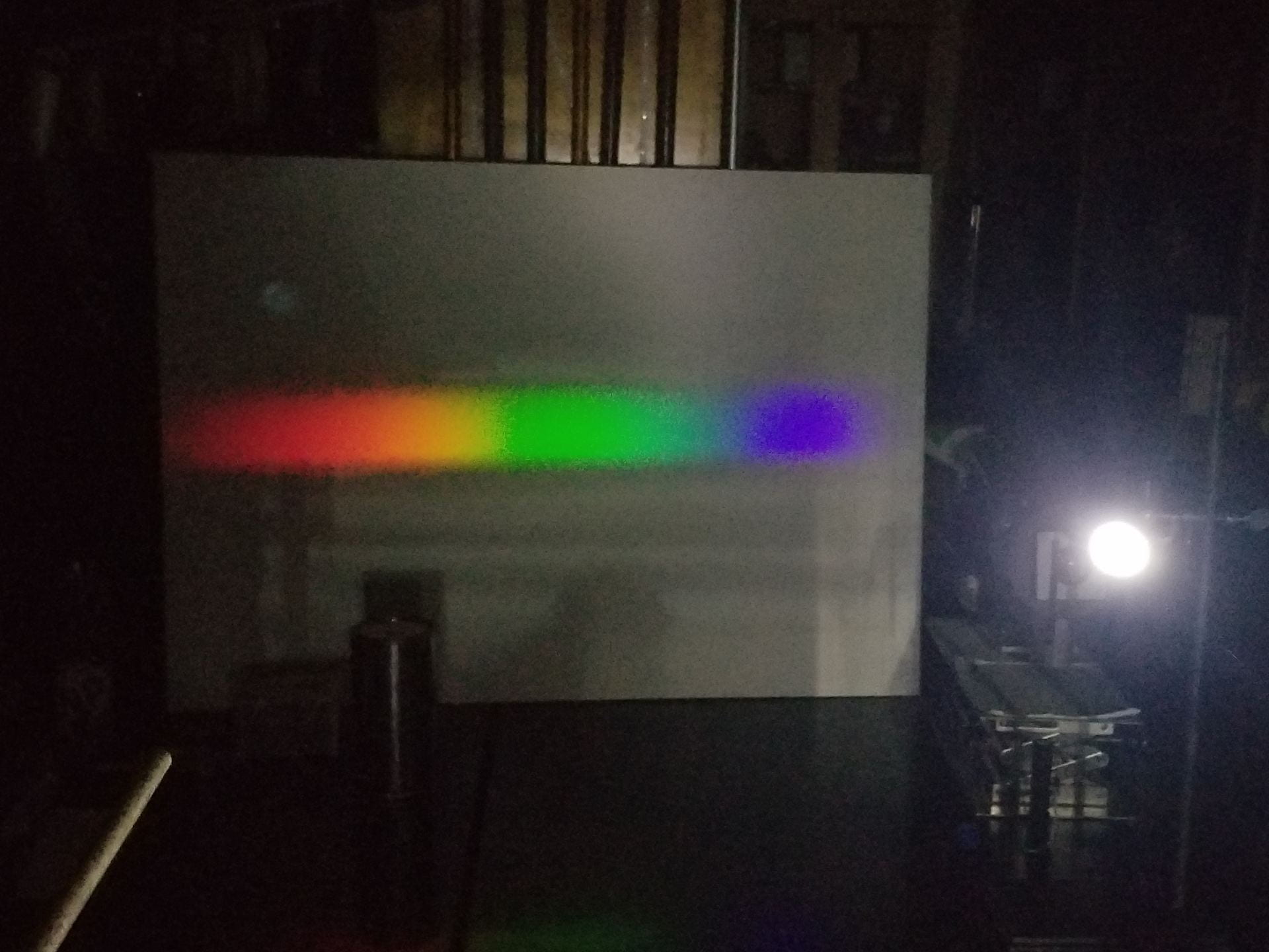
Figure 11: Spectra produced with flashlight and smaller grating
As shown, the smaller diffraction grating produces a wider spectrum than the larger grating, but isn’t quite as tall. This distinction helps choose which grating should be used based on the desired shape of the spectrum, and space available to project the spectrum onto.
This process becomes more flexible when setting up in a larger classroom such as Thimann 1 or 3. The setup for larger classrooms will be described below, using Thimann 1 as an example. The geometry of the setup with carbon arc lamp and large grating are shown below in Figure 12 and Figure 13, while the product of this setup is shown in Figure 14.

Figure 12: Aiming of the carbon arc lamp
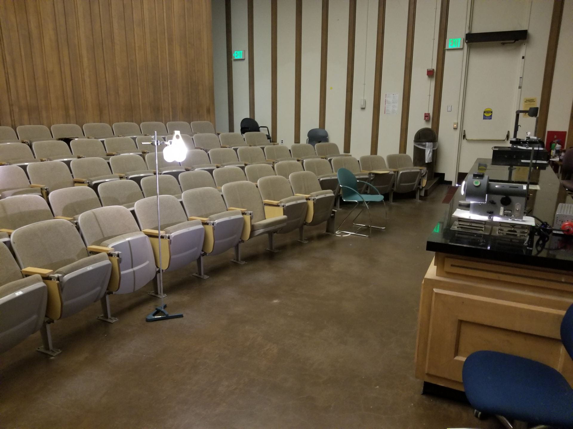
Figure 13: Carbon arc lamp geometry
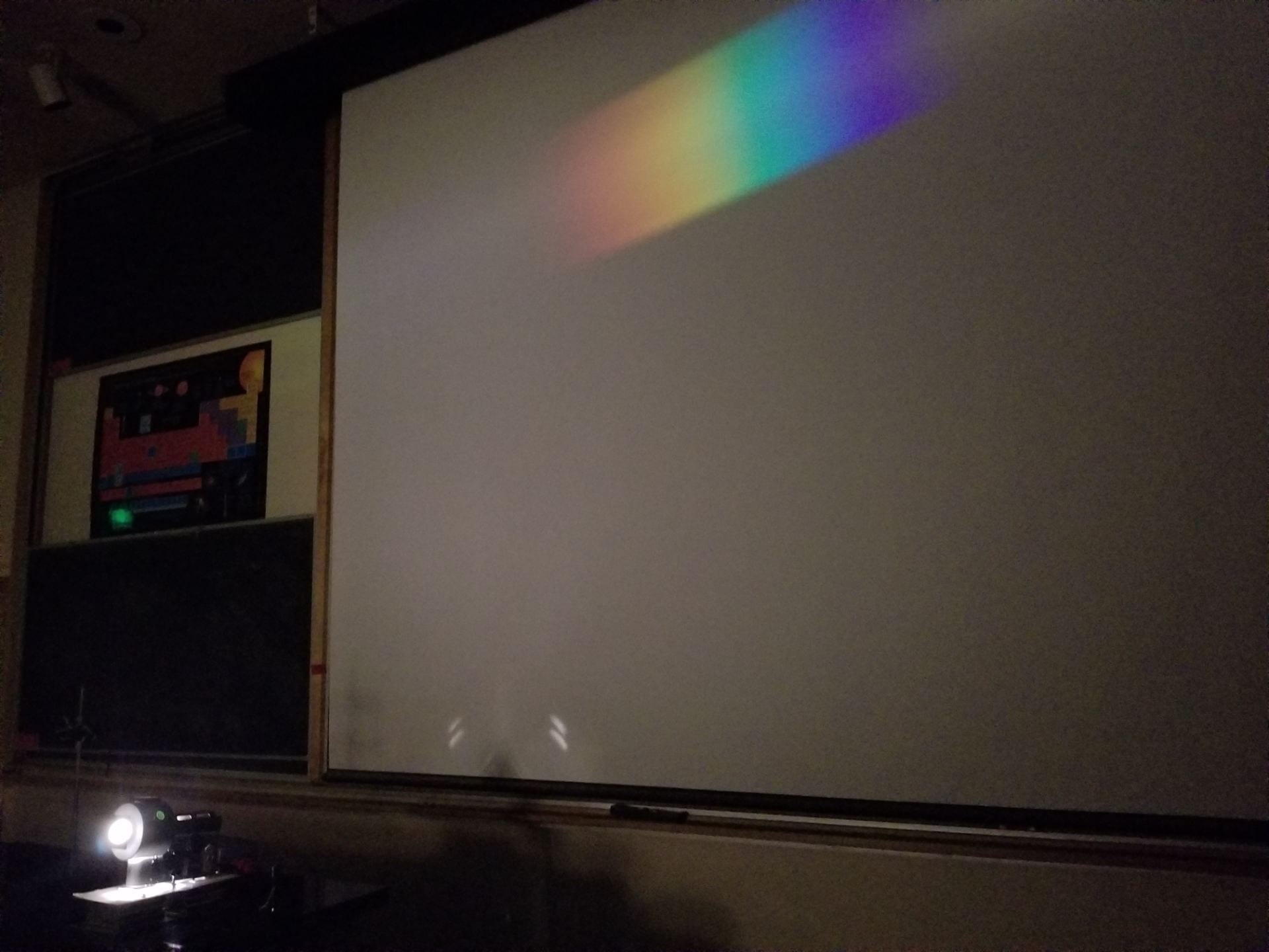
Figure 14: Carbon arc lamp, large diffraction grating projection
As seen in Figure 14, the carbon arc lamp and large diffraction grating are much less adjustable. This leads to difficulty centering the projection on the center of the screen, and produces a lower intensity light than expected for the powerful arc lamp.
The alternative to this combination is to use the flashlight as light source and small diffraction grating along with it. One geometry is shown below in Figure 15, however many more are possible with this pair of light source and grating.

Figure 15: Flashlight and small grating geometry located in the back of the classroom
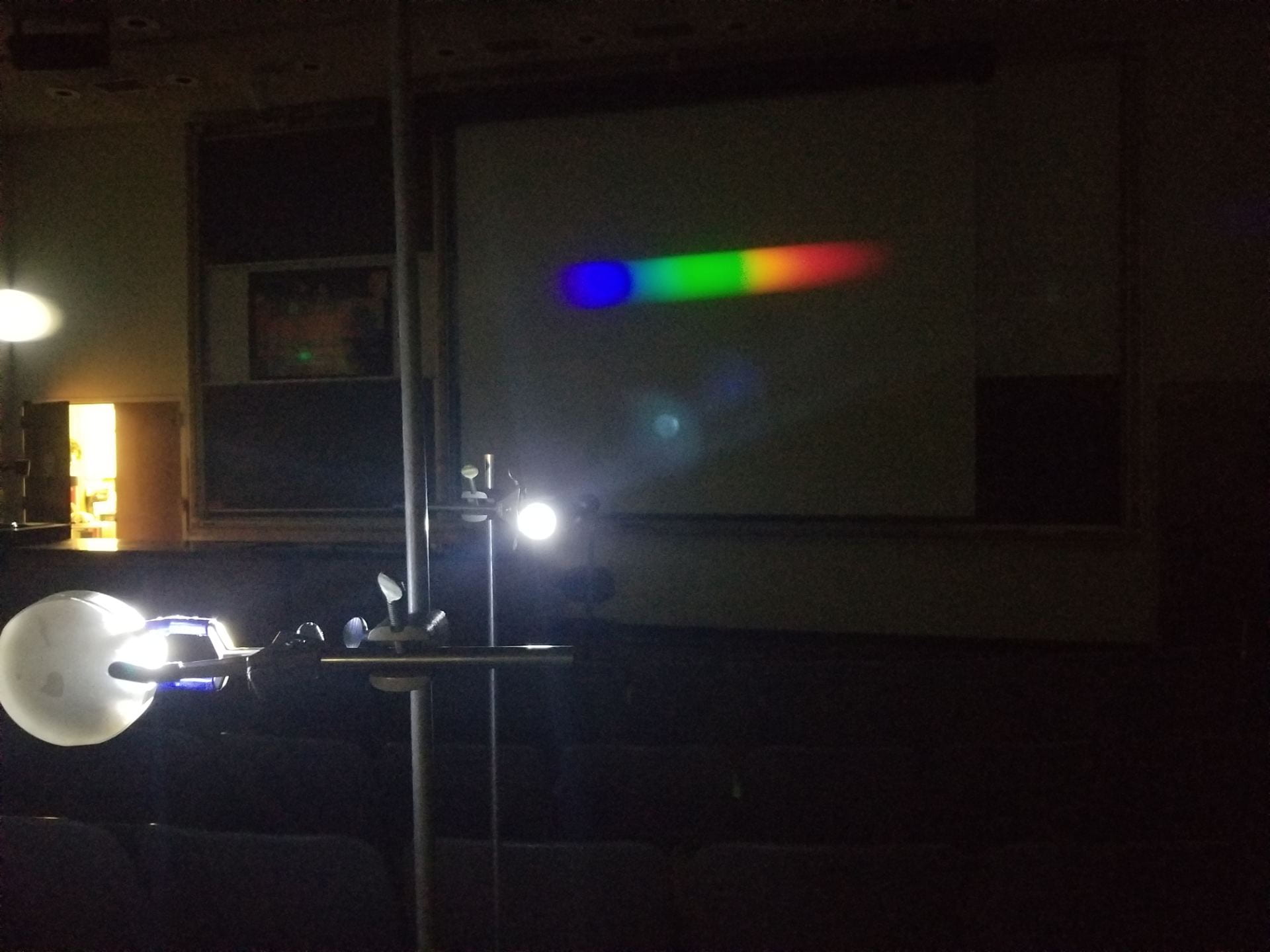
Figure 16: Product of flashlight and small grating
The result of this combination is shown above in Figure 16. I found the ideal separation distance between flashlight and grating to be one to two feet. This produces the highest intensity possible while still demonstrating the full spectrum of wavelengths without distortion. Beyond this limit, this pair can be moved all around the classroom. In larger classrooms it becomes possible to move this pair further back and produce a wider spectrum on the screen.
Notes:
- Increasing distance between light source and grating decreases intensity of reflected light
- Increasing distance between grating and projection screen increases size of projected rainbow
- Circular diffraction grating produces a wide, short rainbow
- The larger 1600 lines/mm grating projects a taller, yet thinner rainbow
- The flashlight produces lower intensity light, but it is highly adjustable
Explanation:
For this demo we’ve made use of a reflective diffraction grating, whose geometry is a slight variant of the standard transmission based diffraction gratings. To illustrate this new geometry a diagram is included below as Figure 17.

Figure 17: Reflective Grating Geometry, from Thorlabs
As the diagram shows, the traditional slits are replaced by platforms tilted at some angle 
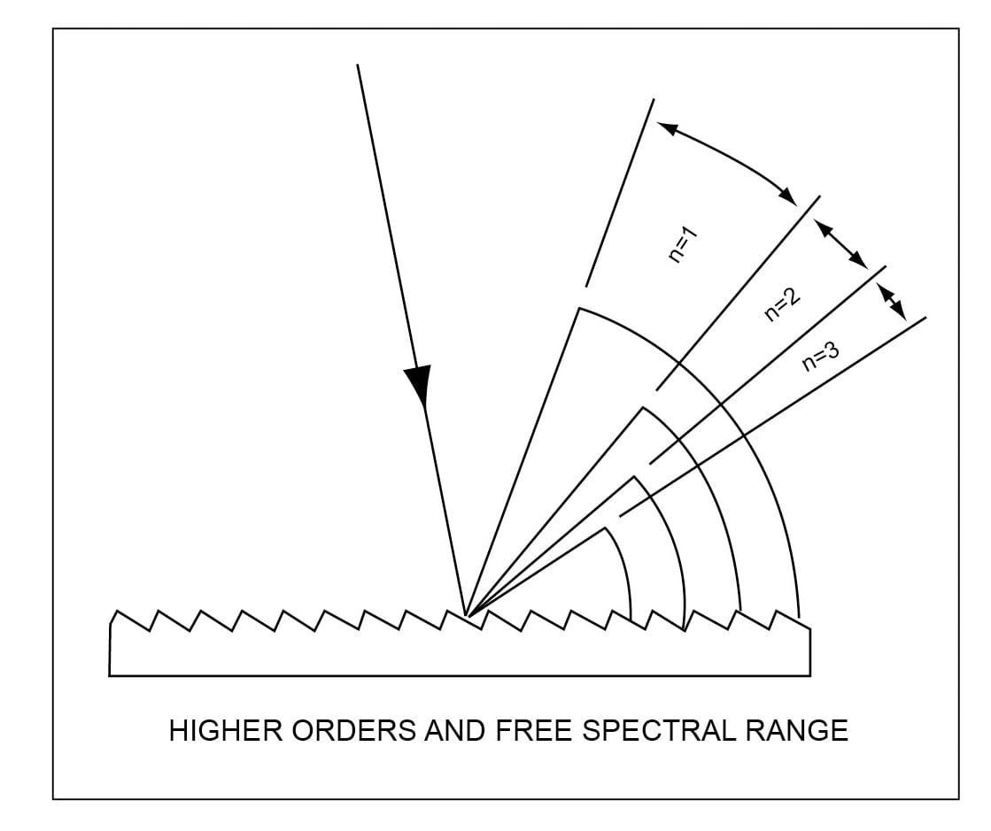
Figure 18: Higher Order Diffractions, from Dynasil
In addition, diffractions are symmetric about the zeroth order for this reflective style grating, where the geometry is shown below in Figure 19.
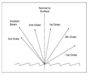
Figure 19: Symmetric Higher Order Diffractions, from Dynasil
With this slightly varied geometry we must produce a new diffraction equation for this specific case. However, we first need one last diagram to clearly label our definitions of incident and reflected angles, shown in Figure 20 below.

Figure 20: Zeroth Order Reflection, from Dynasil
Using these definitions of angle of incidence and angle of reflection based on the zeroth order, we can now produce several useful geometric formulae. In general for reflective gratings,
![a[sin(\theta_I)+sin(\theta_R)]=m\lambda](https://s0.wp.com/latex.php?latex=a%5Bsin%28%5Ctheta_I%29%2Bsin%28%5Ctheta_R%29%5D%3Dm%5Clambda&bg=ffffff&fg=000000&s=0 "a[sin(\theta_I)+sin(\theta_R)]=m\lambda")
For normal incidence, 
For our case shown above with gratings angled at

This allows us to make the following simplification for normal incidence,
=m\lambda")
Using these equations we can now explain the rainbow created by reflecting light off the provided reflective gratings. We start with the flashlight using an LED to produce light, or the arc lamp which arcs electricity between two pieces of carbon to produce its light. In either case, these light sources produce a full spectrum of visible light along with other wavelengths undetectable to our eyes.
Once this beam strikes a diffraction grating at normal incidence, it is reflected according to =m\lambda")
Each separate wavelength is incident at the same angle, because they come from the same point source. However, once they strike the reflection grating, each is reflected at a different angle in the visible first and second orders. This wavelength based reflection is what separates each wavelength and produces the large rainbow visible on the projection screen.
Written by Noah Peake