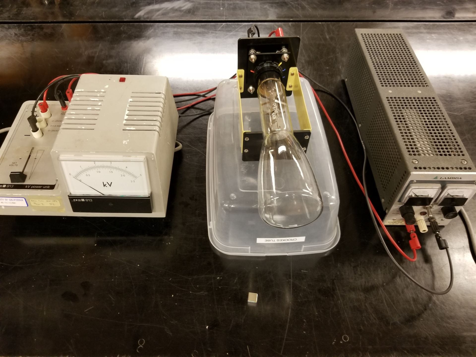
Figure 1: Crookes tube is on the right, and the kV power unit is on the left.
A large transparent Crookes tube, shown in Figure 1, filled with low-pressure hydrogen gas makes a clearly visible beam of electrons, which is shown in Figure 2. The beam is deflected with a magnet placed near the tube or by applying voltage to the deflection plates inside the tube. The power supply has a 6.3V AC output for the cathode and a variable DC output for the anode.
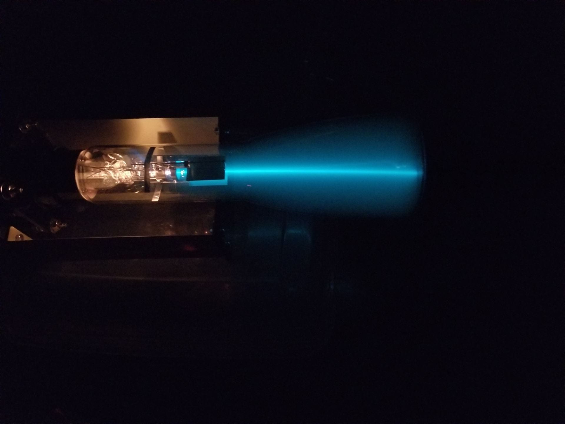
Figure 2: Cathode ray produced by the filament in the Crookes tube.
Note:
The room should be darkened to make the beam visible.
Equipment:
- Crookes Tube [Cabinet D2]
- kV Power Unit (Model No.: 85-70-02443) [Cabinet K]
- Lambda Power Supply (Model No.: 60-70-00719) [Cabinet K]
- 6 Banana Cables
- Magnet
- Video Camera (for large classes)
Demo:
- Attach banana cables from the 6.3V terminals on the kV Power Unit to the 6.3V terminals on the Crookes tube, i.e. top two slots.
- Attach banana cables from the variable voltage terminals on the kV Power Unit, which are labeled by “+” and “-“, to the DC voltage terminals on the Crookes tube, i.e. the middle two slots.
- Attach banana cables from the terminals on the Power Supply to the bottom two slots on the Crookes tube.
- Ground the circuit by attaching a banana cable from the “-” terminal on the kV Power Unit to the ground terminal on the kV Power Unit.
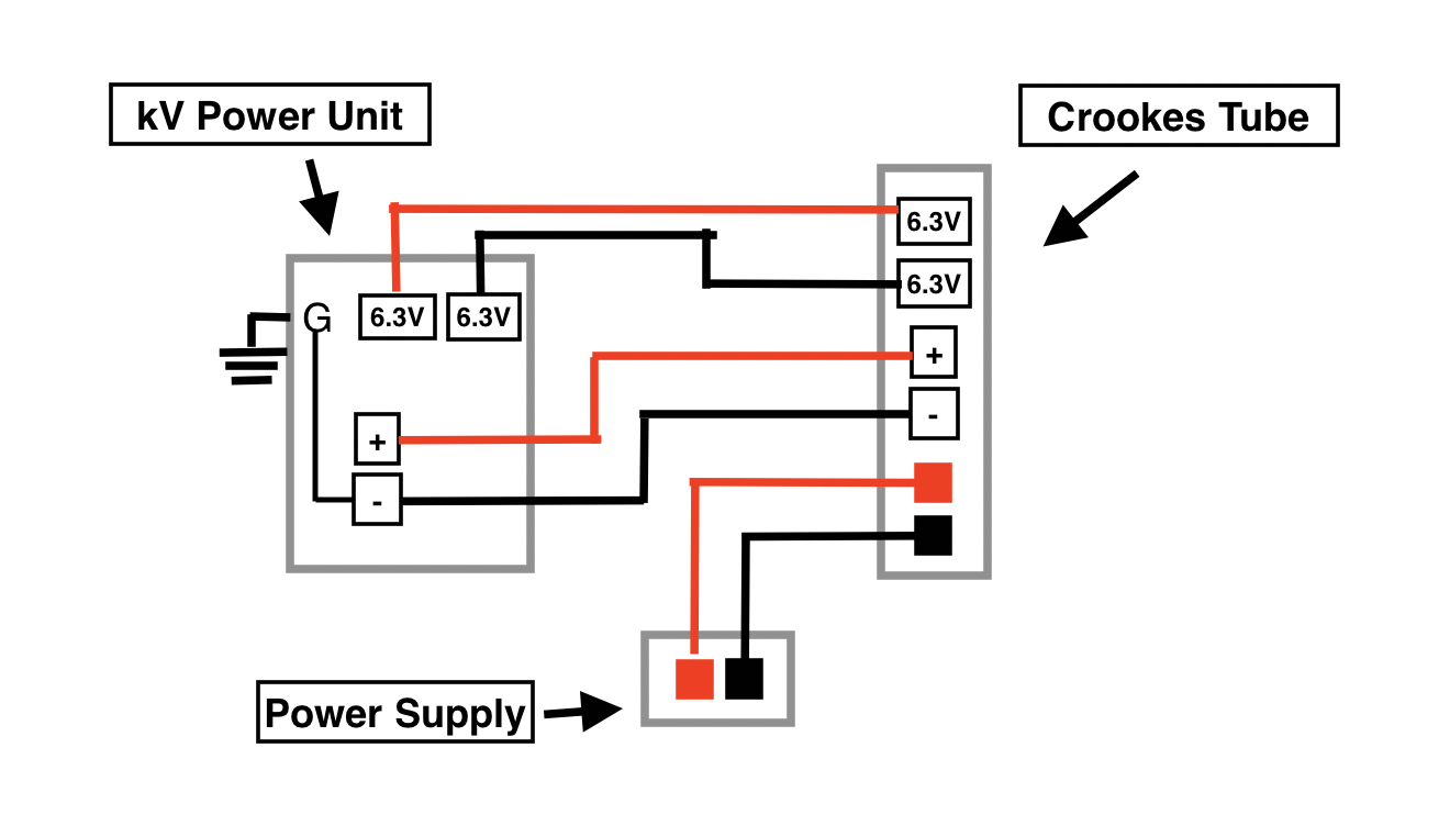
Figure 3: Circuit schematic of the Crookes tube demonstration.
The completed circuit for the Crookes tube is shown in Figure 3. Once the set up for the Crookes tube is complete, turn on the kV Power Unit and leave it on for a minute so that the filament in the Crookes tube heats up. The filament will glow orange as it heats up. Once it is heated up, slowly increase the variable voltage on the kV Power Unit until you are able to see the cathode ray.
At this point, the cathode ray (beam of electrons) should travel in a straight line from the cathode to the anode. Inside the Crookes tube, there is a second pair of metal plates that are placed on either side of the cathode ray. Applying a potential difference between these two plates will create an electric field and cause the cathode ray to bend in the opposite direction of the electric field, which is shown in Figure 4.

Figure 4: The deflection of the cathode ray due to a potential difference between the two metal plates inside of the Crookes tube.
Make sure that current and voltage of the power supply are set to zero prior to turning the power supply on. Turn on the power supply and set the current to 0.3A, and slowly increase the voltage of the power supply. This will create the potential difference between the two metal plates inside of the Crookes tube and cause the cathode ray to bend. To have the cathode ray bend the other way, turn the current to 0A on the power supply, and then simply swap the banana cables that are only on the Crookes tube.
In Figure 4, a potential difference is created between the two metal plates inside of the Crookes tube. This results in an electric field that points from the positive metal plate to the negative metal plate. This electric field acts on the cathode ray, causing it to deflect towards the positive plate, due to the negative charge of the electron. If the electric field was reversed, the cathode ray would deflect in the opposite direction.

Figure 5: The cathode ray is deflected by a magnetic field.
To bend the cathode ray with the magnet, simply bring the magnet near the cathode ray. If a magnet is introduced near the Crookes tube, a force will be exerted on the cathode ray that is perpendicular to both the direction of the velocity of the electrons and the direction of the magnetic field. This is shown in Figure 5.
Explanation:
The Crookes tube used in this demo is a partially evacuated glass bulb that contains a low-pressure hydrogen gas. On one end of the Crookes tube, there is a metal electrode. This contains a cathode and an anode. A high voltage applied between the electrodes creates a voltage and an electric field, where the negative end is the cathode, and the positive end is the anode. The cathode contains a filament, such that when it’s temperature increases due to the high voltage, a high number of electrons are released from the surface of the cathode. These emitted electrons are then accelerated on a straight path towards the anode by the electric field. This beam of electrons traveling from the cathode to the anode is known as a cathode ray. The anode allows the cathode ray to pass through and continue on in a straight line until it hits the end of the Crookes tube.
The path that the beam of electrons follow can be altered by the Lorentz force. The Lorentz force is the combination of the force that an electric field and a magnetic field exerts on a point charge
")
where e is the charge of an electron, 


If only an electric field is applied across the cathode ray, the beam of electrons will feel a force exerted on them in the opposite direction of the applied electric field:

If only a magnetic field is applied across the cathode ray, the beam of electrons will feel a force whose direction is give by the curl of the velocity and the magnetic field:
")
The cross product between the velocity of the cathode ray and the external magnetic field results in a force that is perpendicular to both the velocity of the cathode ray and the external magnetic field. The direction of the force from the external magnetic field can be determined by the right hand rule. Keep in mind that the charge of an electron is negative. This causes the direction of the force to point in the opposite direction. The correct direction of the force could also be done by using the right hand rule, but with your left hand; this takes into account the negative sign from the charge of the electron.
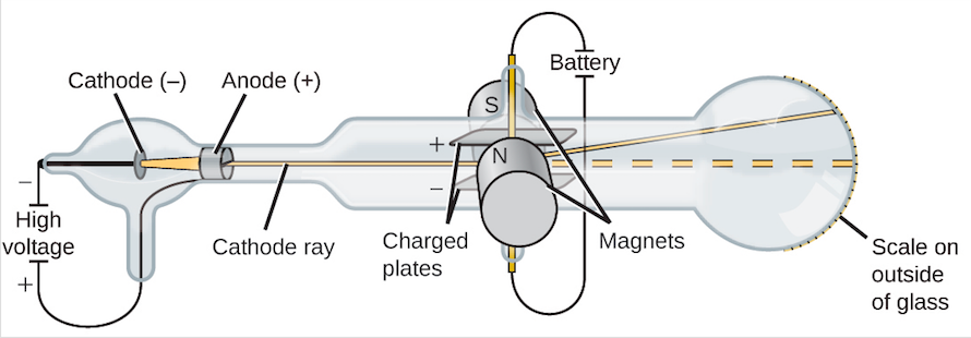
Figure 6: Deflection of the cathode ray due to an applied external electric field and an applied external magnetic field.
The Lorentz force describes a force that is provided by both an electric field and a magnetic field. In this demonstration, the Lorentz force can be shown by applying a potential difference between the two plates that are inside of the Crookes tube, and holding a magnet near the end of the Crookes tube where the cathode ray is located. The Lorentz force acting on a cathode ray is shown in Figure 6.
Written by Ryan Dudschus