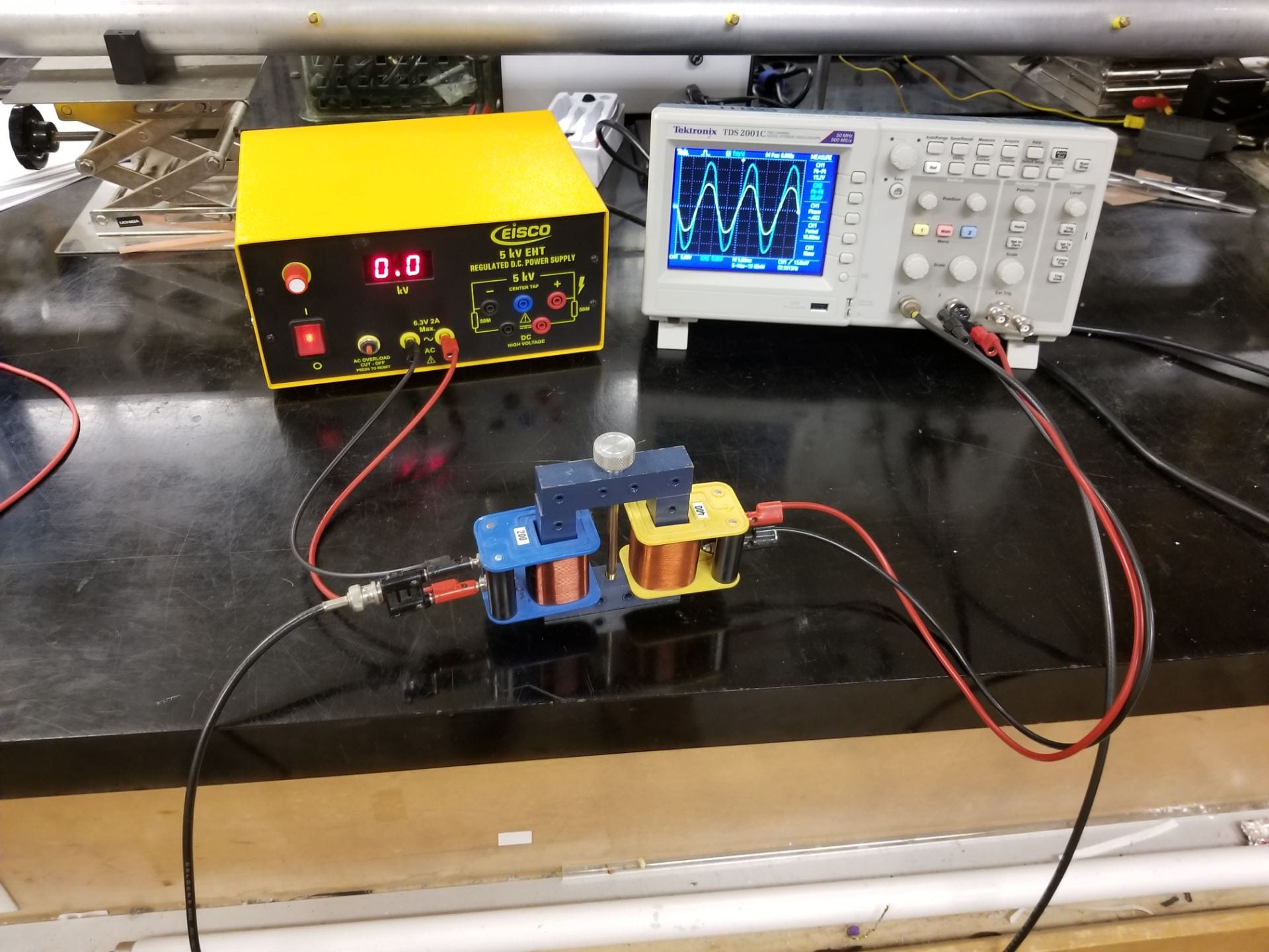
Figure 1: Transformer Circuit
Coils with different number of turns allow the instructor to set up several step-down and step-up transformer circuits. The ratio and phase difference between Vin and Vout can be seen on the oscilloscope.
Materials:
- Transformer with interchangeable coils –
200 turns (1), 400 turns (2), 800 turns (1):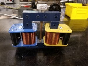
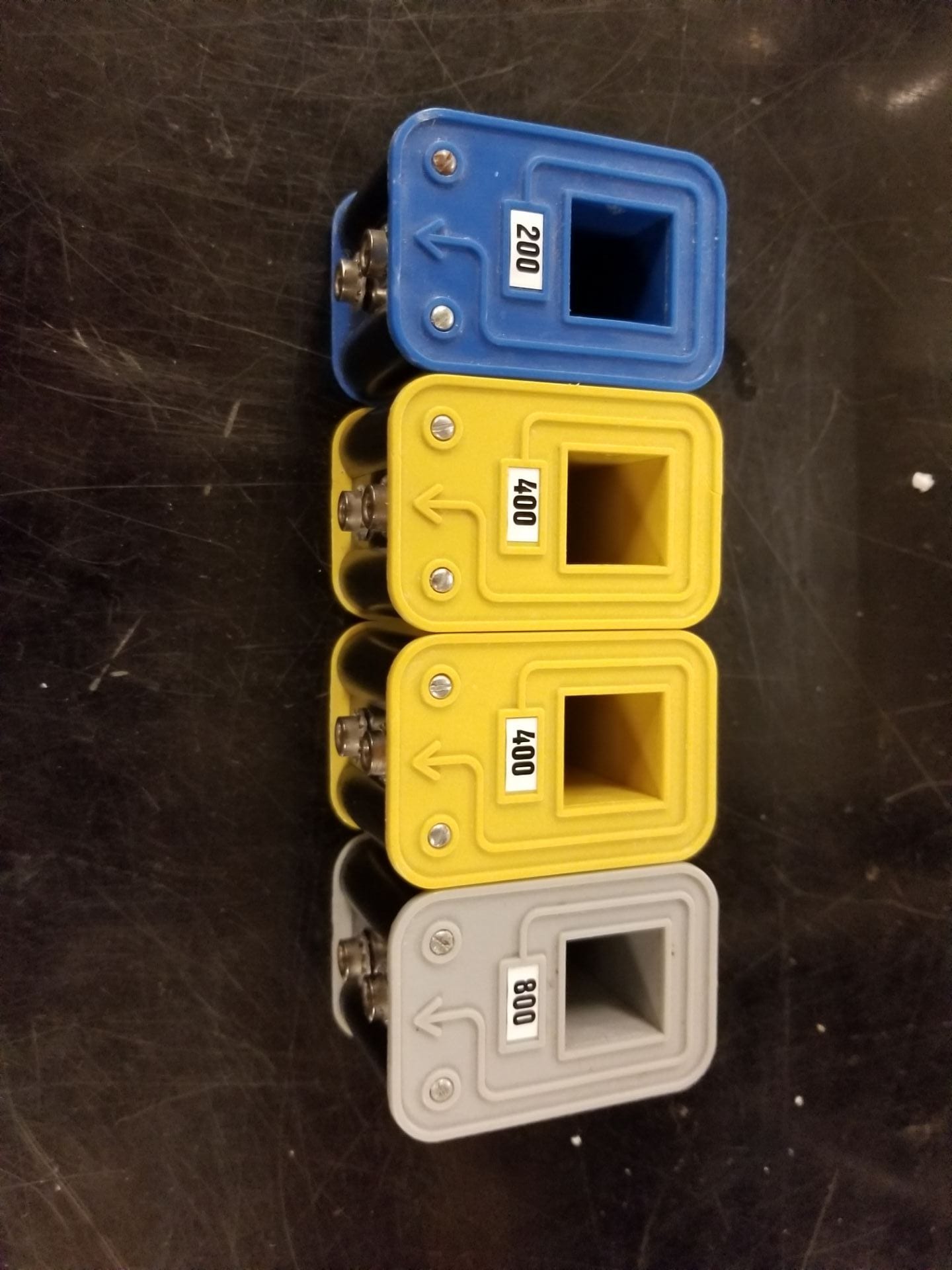
Figure 2: Transformer Components

Figure 3: Coils with various numbers of turns
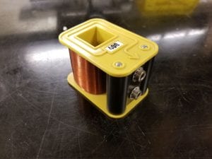
Figure 4: One coil assembly
- High power function generator:
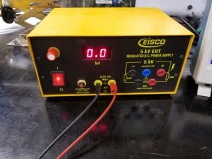
Figure 5: Eisco Function generator
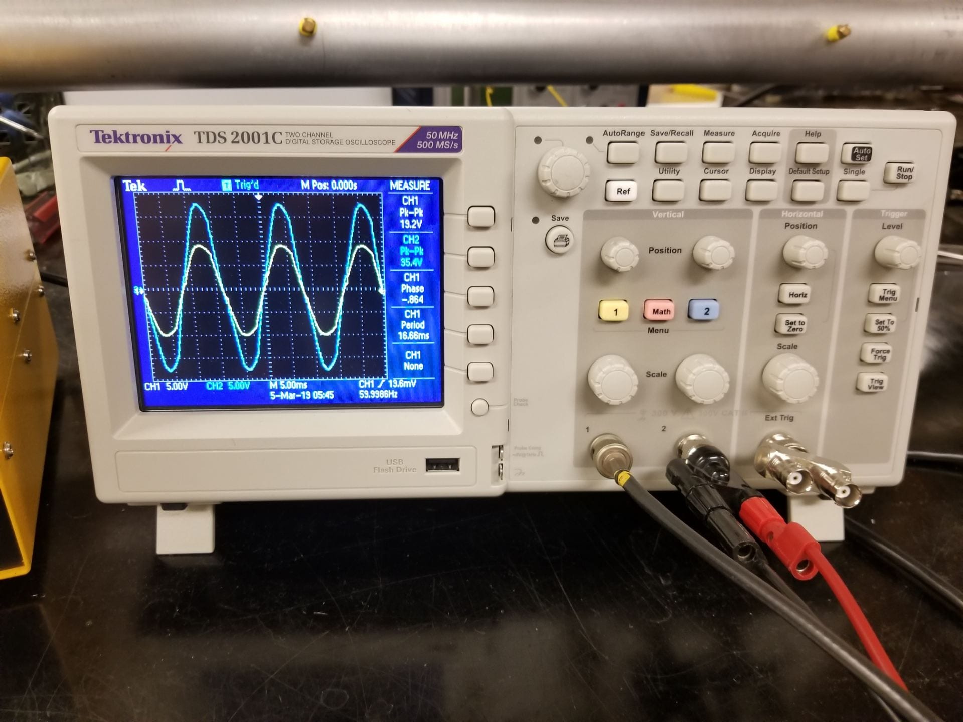
- Oscilloscope:
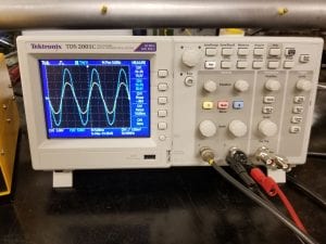
Figure 6: Oscilloscope
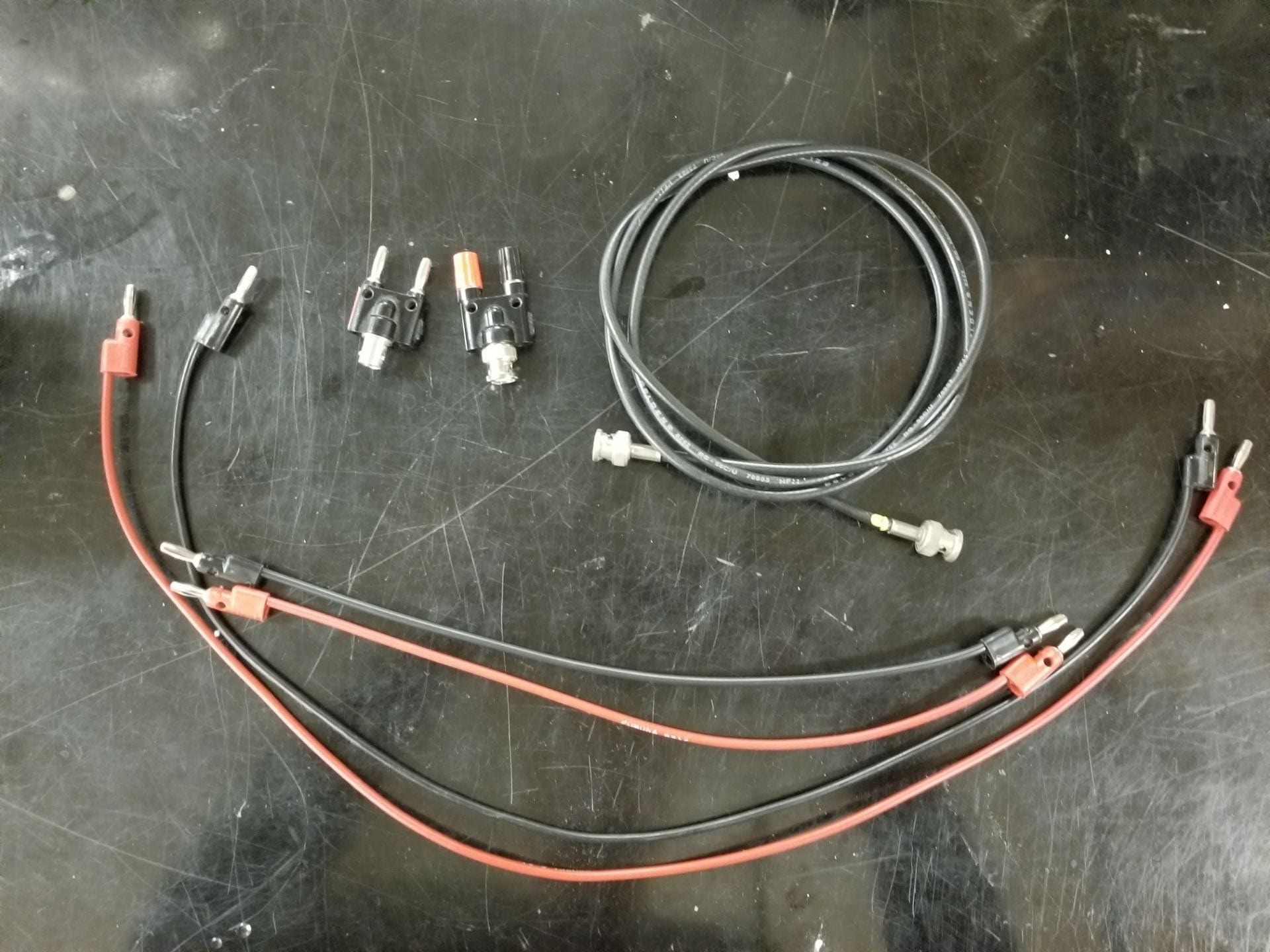
- Additional connection cables:

Figure 7: Cables required for various connections
- Video camera


Setup:
The setup for this demo is fairly simple. Each coil has two female banana jacks. One pair of banana cables needs to go from the function generator to the first coil. The other pair of banana cables goes from the second coil to the oscilloscope channel 2. And finally, the input provided by the function generator must also travel directly to the oscilloscope channel 1. This is done with the male banana jack to BNC converter and female banana jack to BNC converter. In addition, a circuit diagram is shown below.
Figure 8: Transformer Setup Circuit Diagram
The other process involved with this demo is switching out the coil assemblies to observe effects with varying numbers of coils. To do this we’ll refer to Figure 2 above. First loosen the silver fastener on top, but doesn’t need to be fully removed. Once loose, twist the top blue metal piece 90 degrees and let it fall between the two coil assemblies. Then remove one or both of the coil assemblies and replace them.
Explanation:
For the explanation of this device we first introduce a general model of the transformer.
Figure 9: Standard Transformer Model from Wikipedia
The model of Figure 8 will allow us to begin calculations to determine the ratio of voltages as a function of the number of turns for each coil. First, the leftmost coil is the primary coil with voltage 


Where 

Using this equation we can then solve for 


Here we have derived an equation for the relationship between two wire windings with a shared core. This can be easily applied to our situation with several small naming changes.

In this equation it is important to note that the output voltage will be observed through channel 2 of the oscilloscope, while the input voltage is observed on channel 1. Similarly, 

The input voltage is modified by the ratio of turns of the output over turns of the input. Our coil assemblies only come with 200, 400, or 800 turns. This leaves us with an input voltage multiplication of .25, .5, 2, or 4 depending on the specific combination of coils used.
These values can be verified on the oscilloscope using the measure function. There are four sections that can be set, but we’ll only need two in this case. Simply set one to the peak to peak of channel one, and the second section to the peak to peak of channel two. Remember that channel one is the input voltage, while channel 2 is the output voltage. With these two numbers we can confirm our calculations above, and verify the process by which transformers either step up or step down voltage using series of windings.
Written by Noah Peake