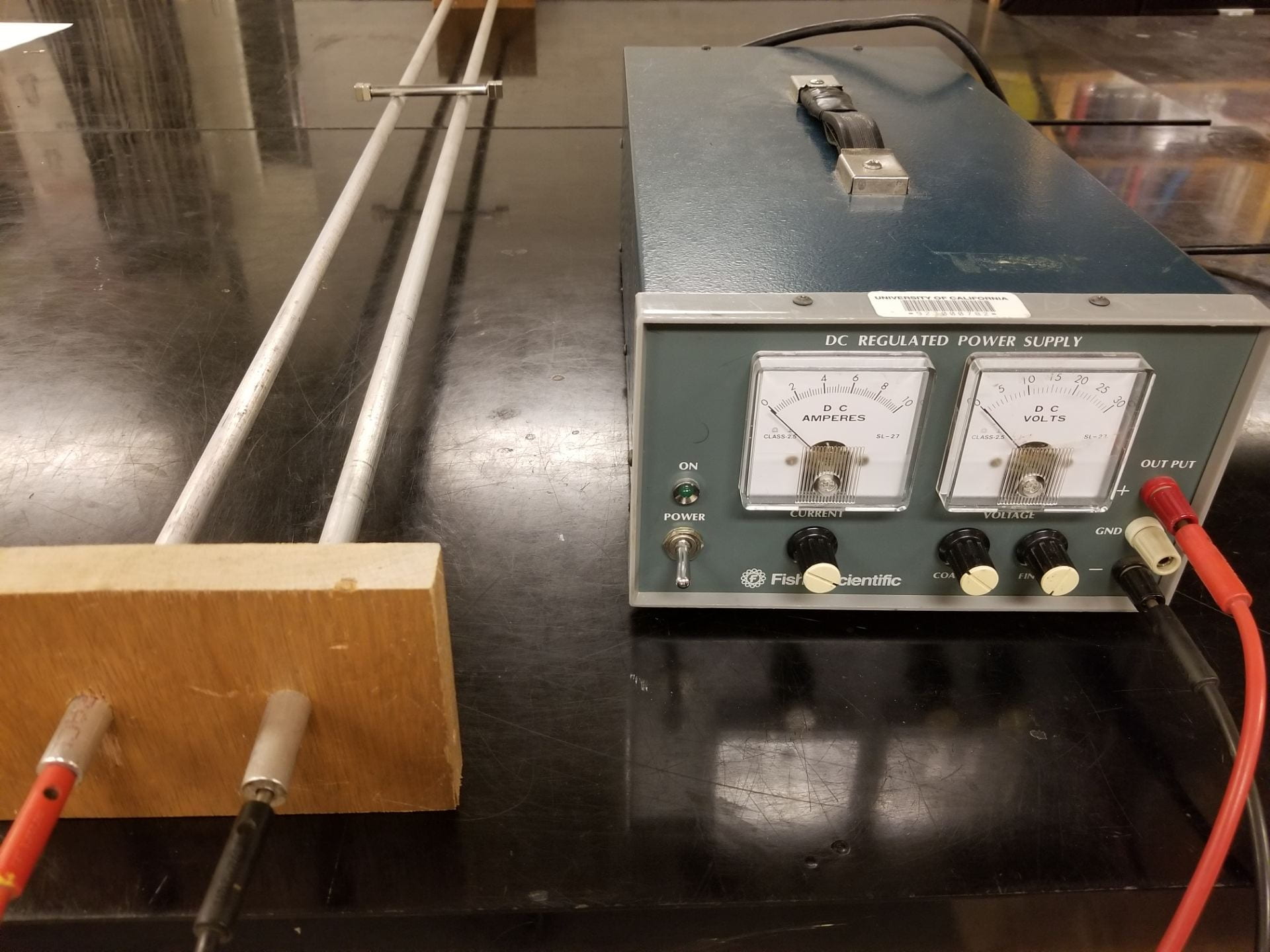
Figure 1: Rail gun setup

Figure 2: Rail gun in action
This demonstration showcases one of the practical applications of the Lorentz force with a small steel rod being accelerated along a track using a large current. While this version of rail gun doesn’t launch the projectile as a practical rail gun would, it is still dangerous due to the large currents involved in moving the projectile. The demo should only be performed by trained demo room personnel, and only after thoroughly reading the safety section.
Materials:
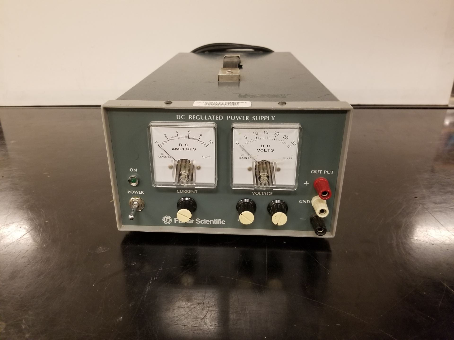
- Fisher Scientific power supply — Supplies the low voltage, high voltage to accelerate the central steel rod. [Cabinet K4]
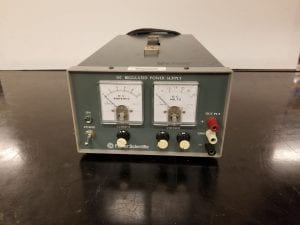
Figure 3: Fisher Scientific power supply
- Rail gun bundle — This contains the smaller steel rod, magnets, and aluminum rod stands. [Cabinet F2]
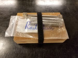
Figure 4: Rail gun demo bundle
- Aluminum rods — These long aluminum rods are what the steel rod will roll along, and be held up by the stands in the rail gun bundle. [Stand near cabinet F]
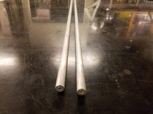
Figure 5: Aluminum rods with banana jack holes
- Personal protective equipment — Insulating gloves and insulating mat. [Below glassware]

Figure 6: Insulated gloves

Figure 7: Insulating floor mat


Setup:
- Insert the aluminum rails into the stands, with one stand at each end of the assembly. Make sure that the stands are in the correct orientation to keep the rails level.
- Plug in the power supply.
- Use the banana cables to connect the Fisher power supply to the rails.
- Attach two or three neodymium magnets to either end of one of the steel rods, if not already attached. The magnetic fields should be aligned such that there is a uniform field between the magnets on either side, orientation is crucial.
- Lay down the insulating mat where you, the demonstrator, will be standing.
- Put on the insulating gloves, increasing your resistance to the electricity.
- Turn on the power supply, set the voltage to 2.5 volts, and ensure that the current knob is turned fully counterclockwise for 0 amps.
- Position the steel rod onto the aluminum rails, ensuring that it is as straight as possible to allow for the longest run.
- When ready to show the effect, turn the current to the full 10 amps.
- If the projectile doesn’t move, check the orientation of the magnets and try again.
- If the projectile moves opposite to the desired direction, safely reverse the polarity of the voltage from the power supply.
- To make the projectile return to you, reverse the polarity of the supplied voltage and turn the current back up to accelerate it in the opposite direction.
Safety:
- This demo is dangerous, and should only be performed by properly trained demo room personnel.
- Wear the proper PPE when performing this demo.
- ie: insulating gloves, insulating floor mat
- Only supply the full 10 amps when acceleration is desired, return it to 0 amps when not actively being used.
- This will prevent accidental shocks, premature wear on the components, and waste less power.
- Only touch the projectile or the rails once the power supply is at 0 volts, 0 amps, and turned off. This includes when reversing the polarity of voltage by removing banana jacks from the power supply.
- Make sure the immediate area is clear of students so that no one accidentally touches the rails without proper PPE while power is being supplied.
Explanation:
The physics behind this demo relies on current passing through a magnetic field and the Lorentz force to cause motion, similar to the homopolar motor. Figure 8 below provides a visualization of the current path and direction of magnetic field.
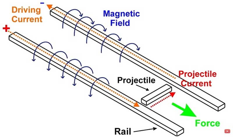
Figure 8: Rail gun diagram, from Hacksmith
Current travels from the power supply, down one rail, through the projectile, and back through the other rail to the return of the power supply. The direction of magnetic field produced by this current follows right hand rule with magnitude,

This magnetic field turns out to be too small to produce a noticeable effect, so small neodymium magnets are added to the steel rod to increase the field in the immediate area. The current flowing through the steel rod projectile passes through this magnetic field, resulting in a Lorentz force,
 = I\int \vec{dl}\cdot \vec{B}")
where 

Another, more subtle affect plays a role in this process through Lenz’s law. This law describes the response of a system when the magnetic flux of a closed loop changes. Where magnetic flux is given by

with an induced Emf of

when this flux is changing. In this case, B is constant in time but the effective area enclosing that magnetic field increases as the steel rod rolls along the rails. From this we expect an induced Emf which opposes the increasing magnetic flux and therefore the movement of the steel rod. This may be concerning, as it tells us that the projectile shouldn’t be able to accelerate due to this opposing effect. However, we must also consider the operation of the power supply. Its job is to keep the rails at a fixed voltage, and is capable of supply more power to keep it constant. In the end, this induced Emf simply draws more power from the supply, which is the very power used to accelerate the projectile.
Written by Noah Peake