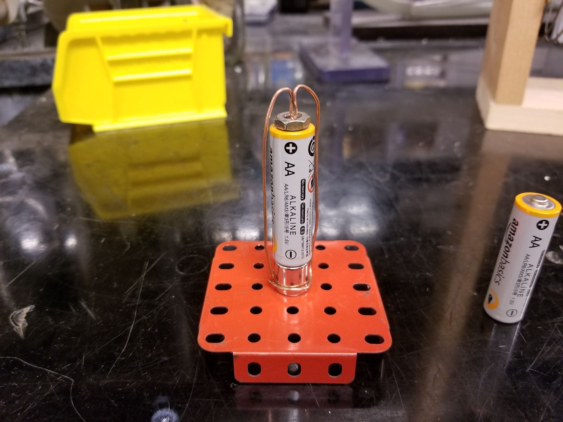
Figure 1: Homopolar Motor Setup
This homopolar motor provides a compact way to demonstrate the effects of the Lorentz force acting on moving charges in a magnetic field.
Materials:
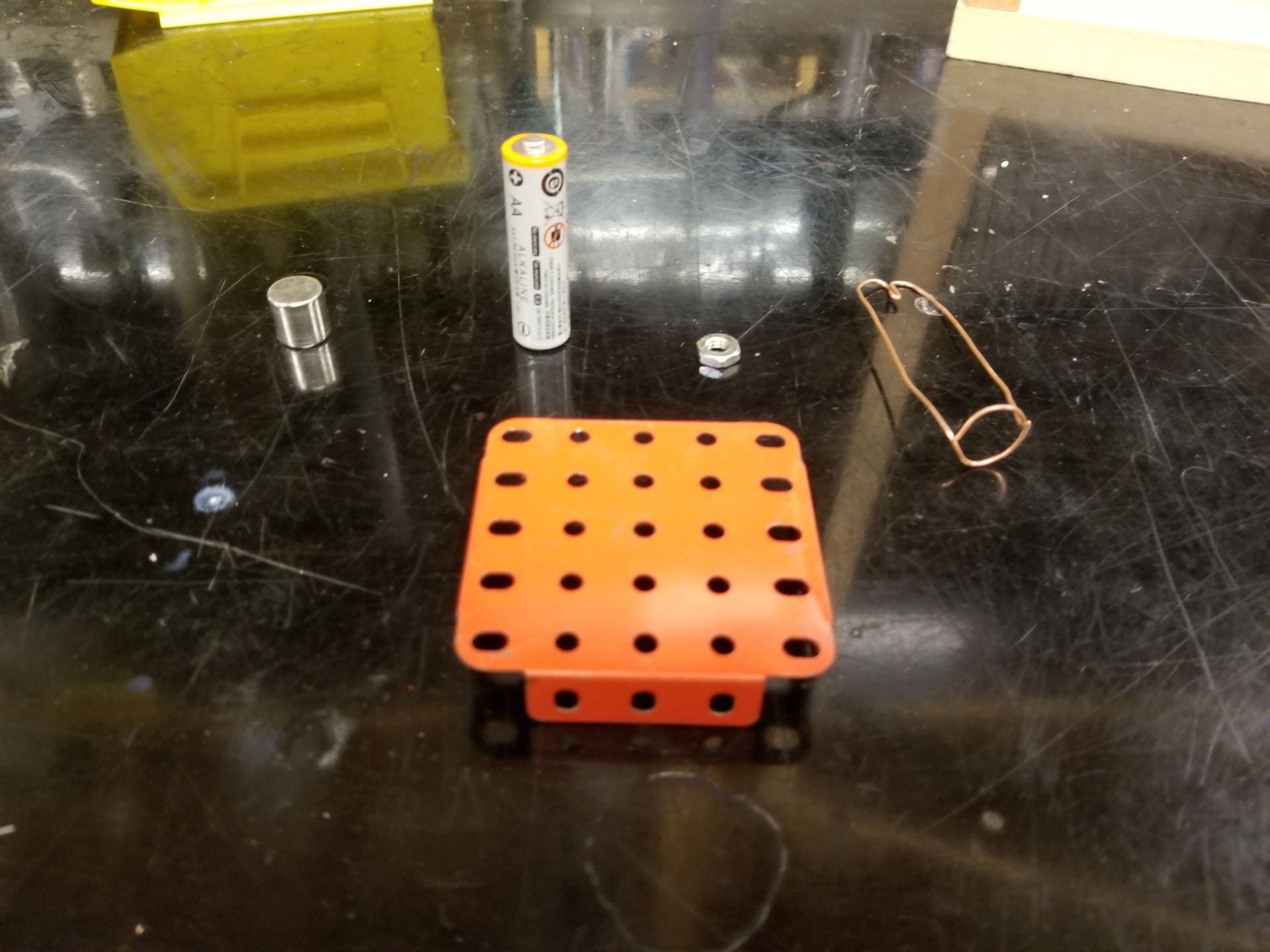
- Homopolar motor bin: Located in cabinet F3. The contents include an AA battery, cylindrical magnet, nut, metallic stand, and two molded copper wires. These components are shown below in Figure 2 and Figure 3.

Figure 2: Homopolar Motor Components

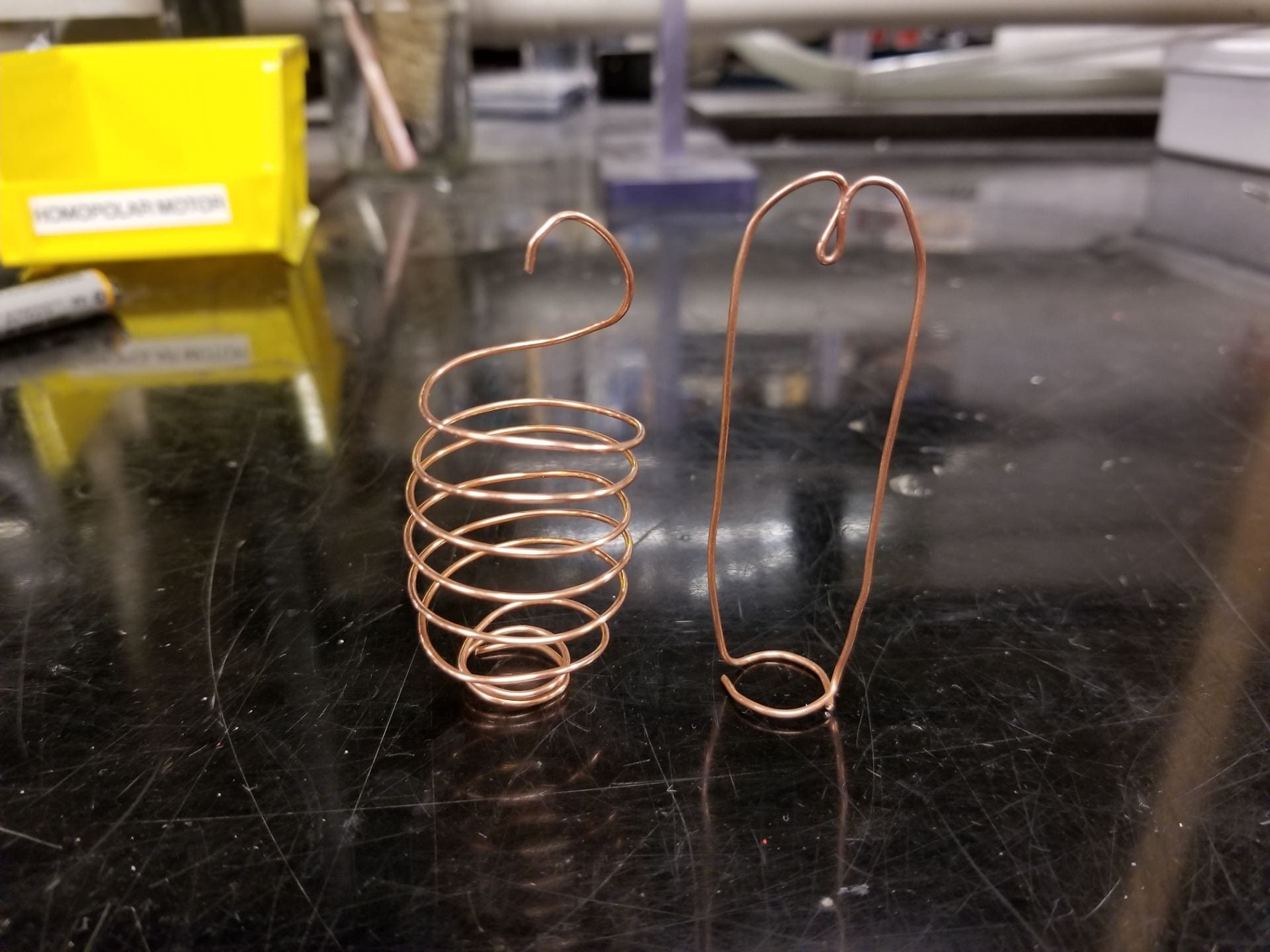
Figure 3: Copper Windings
- Video camera: This demo is particularly small so the video camera will almost always be required.
Setup:
The general setup can be seen above in Figure 1. The order of components progressing upwards is metal stand, cylindrical magnet, battery, nut, and either of the copper windings on top. Either copper winding should spin properly, but may require slight adjustment to maintain good contact with both ends of the battery without causing too much friction. Due to the configuration of the spiral winding it requires slightly different steps to place the components.
First place the metal stand down with the magnet attached. Then place the small cylindrical wrapping of the spiral winding around the magnet. Now insert the battery through the top of the spiral winding. And finally, place the pointed end of the spiral winding onto the positive terminal of the battery to watch it spin.
Explanation:
The homopolar motor spins by turning the electrical energy stored in the battery into kinetic energy by the Lorentz force. The Lorentz force states:

To simplify our calculations we begin with the rectangular winding and later extend the same argument to the more complicated spiral case. Below is a diagram of this wire configuration with B drawn in purple and current flowing downward. This current results from connecting the positive and negative terminals of the battery.

Figure 4: Homopolar motor with B and F labeled, from ResearchGate
From the Lorentz force law stated above we know that the force will point in the direction perpendicular to both the the magnetic field and the current passing through it. As we can see from Figure 4, this force points out of the page on the right side and into the page on the left hand side. The resulting effect is a clockwise rotation when looking down from above the battery.
A similar effect occurs with the spiral winding shown in Figure 3 above. The cross product still results in a clockwise force, same as the rectangular winding. The difference between the two cases is that the force also has a component in the upward or downward direction due to the wire having both vertical and horizontal components as it spirals around the battery. However, the same net rotation is produced for this winding as compared to the rectangular winding. From a practical point of view, this winding setup will be less efficient and produce a lower maximum rotation speed due to the current component in the vertical direction. Despite this I’ve included the shape to show that this effect will occur for nearly any shape due to the net current flow downward, as long as this current passes relatively close to the magnetic field.
Notes:
- Over long periods of time, the copper wire will oxidize and prevent electrical contact
- To fix this, use a cylindrical file to lightly remove the oxidation from the lower point where the winding will make contact with the magnet
- The winding may require fine adjustment to ensure light contact from the lower exposed copper
- Too tight, and friction will slow or stop the rotation
- Too loose, and the copper won’t make contact to conduct sufficient current
Written by Noah Peake