Version 1
Parallel and series circuits (Version 1)
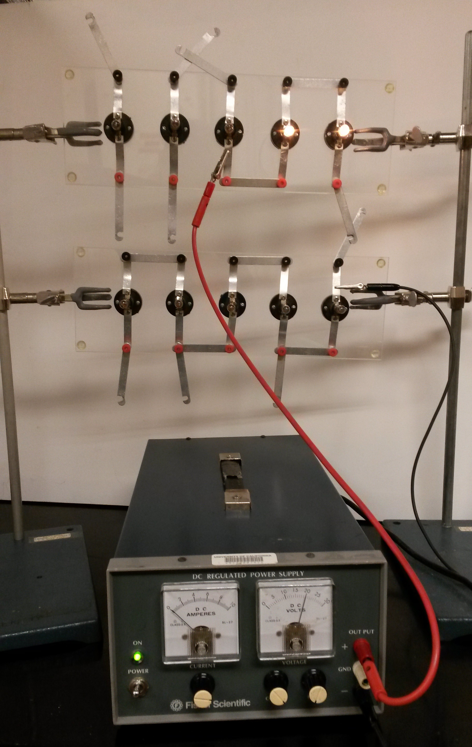
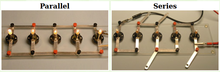
To demonstrate the properties of parallel and series circuits, two boards can be used. The intensity of the lamps’ light shows the circuit’s properties visually. Multimeters can be attached to the circuit to measure voltage and current
Equipment (Version 1):
- Parallel and series circuit boards with stand
- DC regulated power supply (Fisher Scientific)
- Extension cord
- Two banana leads with alligator clips (more can be used if desired)
- Multimeter with leads (optional)
- Video camera recommended for large classrooms
Demo (Version 1):
Possible circuits
- On the power supply, turn the current knob all the way up and the voltage knob all the way down (current-limited mode).
- Hook up the desired circuit using the “+” and “-” inputs on the power supply
- Increase the voltage, and the lightbulbs will light up!
Version 2
We found a new setup in the demo room that works great but does require a bit of practice to be able to switch between types of circuits. The lights are much brighter and it is generally more suited for larger classes! (Pictured below):
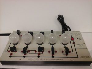
Parallel and Series circuits (Version 2)
While the setup for this is more complicated than for the other demonstration, the lightbulbs on this are much brighter and the difference between series and parallel circuits is much more obvious.
Equipment (Version 2):
- Parallel and series circuits board found in cabinet D shelf 3 (maybe).
- Video camera for large classes
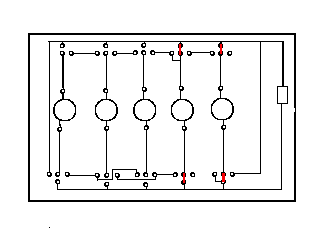
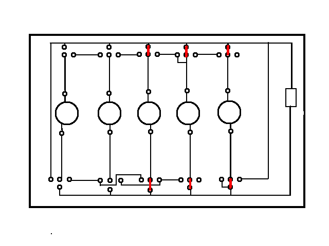
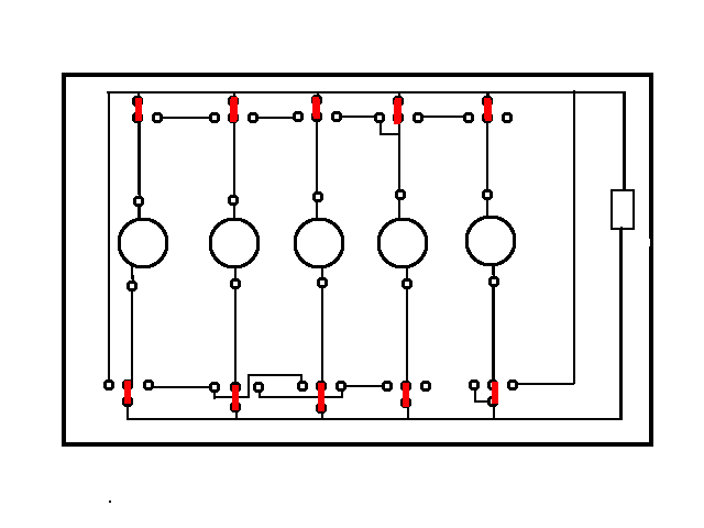
Demo (Version 2): Plug in the board to a normal electrical socket and set up the connections in the format you want to show parallel or series circuits. The most common circuits are shown below, where the red bars show the connections that must be made with the included connection pieces:
Note: The series circuits can be difficult to construct, so it is recommended that the instructor review the demonstration prior to class with demo room manager or one of the assistants. A printout of the possible circuits will also be provided.
-
- 2 in parallel
-
- 3 in parallel
-
- 5 in parallel
-

- 2 in series
-
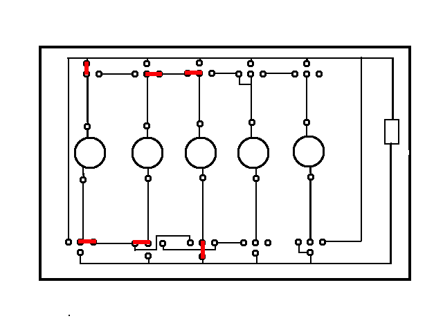
- 3 in series
-
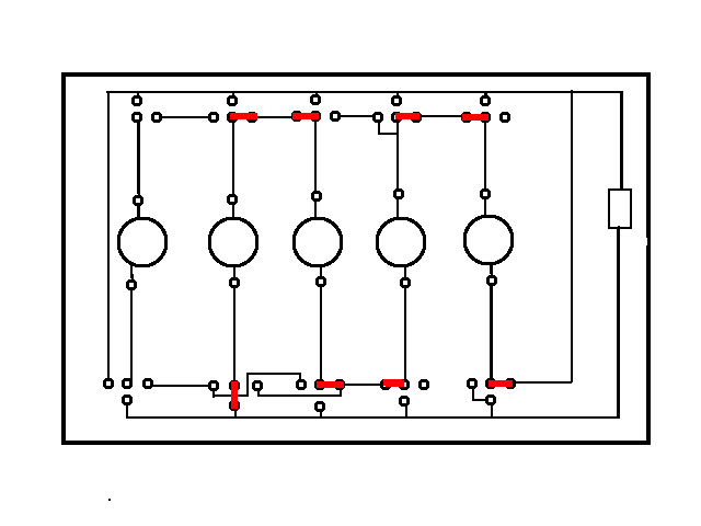
- 4 in series
-
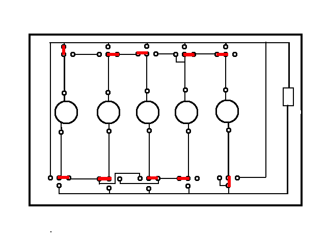
- 5 in series
Explanation:
The brightness of a light bulb depends on its power output (Watts) – a 100 W bulb is brighter than a 40 W bulb. The power (P) can be written as the product of voltage (V) and current (I):
P = IV
Or equivalently:
P = I2R
P = V2 / R
According to the last equation, if only one light bulb is connected across the circuit, the power output will depend on the voltage V dropped across the bulb and the resistance R of the bulb.
If we add another identical bulb in series, the total resistance of the circuit is now 2R. The total power output of the bulbs will be:
P = V2 / 2R
This new total power output is 1/2 of the output with only one bulb – so the bulbs will appear dimmer. As more and more bulbs are added in series, the resistance increases more and more, and the bulbs end up quite dim.
If instead, we add another identical bulb in parallel, the total resistance of the circuit is now R/2. The total power output of the bulbs will be:
P = 2V2 / R
This new total power output is 2 times that of the output with only one bulb – so the bulbs will each have the same brightness; their brightness will be as though they were the only bulb in the circuit! This effect remains the same if you add more and more bulbs in parallel – they will all stay equally bright.
Notes:
- For fewer, brighter bulbs, use version #2
- The Fisher PS goes up to 30 V, which gets the bulbs nice and bright (using the smaller 15 V PS is more convenient but not as bright).
Written by: Sophia Sholtz