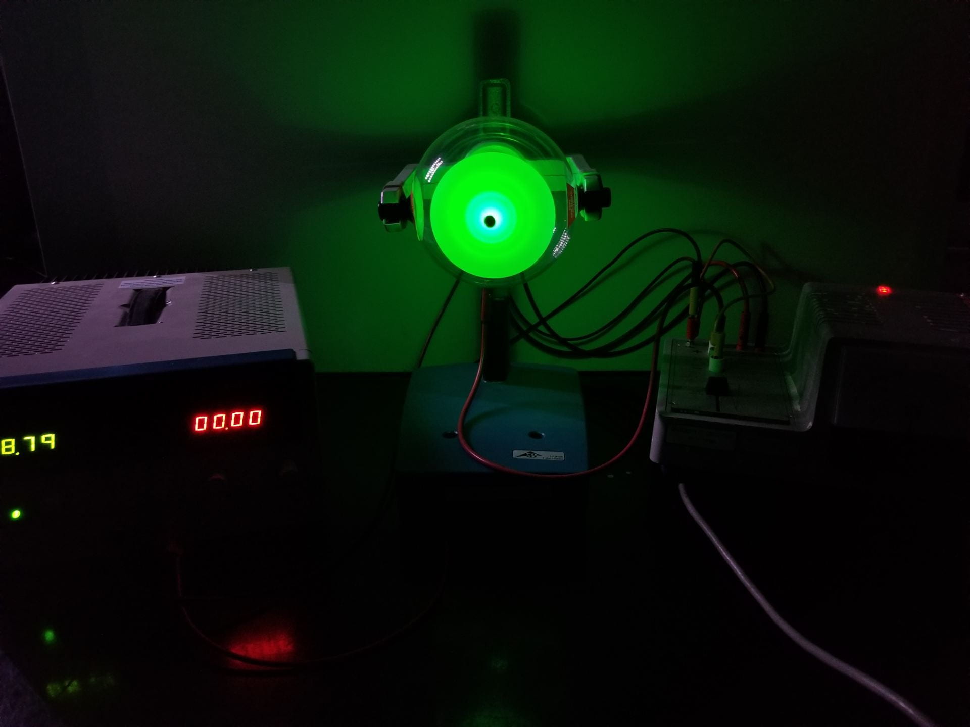
Figure 1: Electron diffraction demo in action
This apparatus shows the diffraction of electrons onto a white viewing screen as shown above in Figure 1.
Equipment:
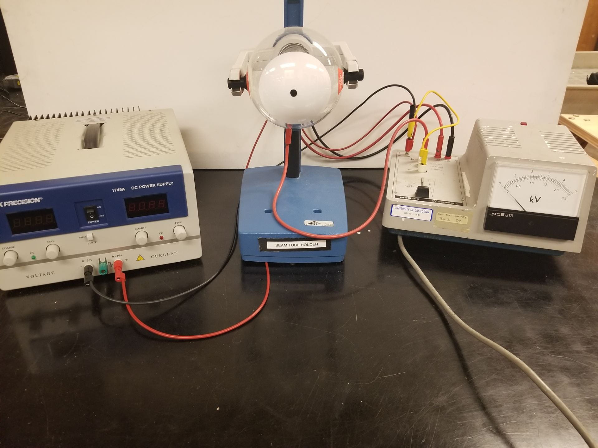
Figure 2: Setup example
- Electron diffraction tube and stand (center of Figure 2) [Cabinet D2]
- Teltron power supply (right in Figure 2) [Cabinet K]
- BK Precision power supply (left in Figure 2) [Cabinet K]
- Banana cables
- Bar magnets
Demo:
Figure 3: Electron diffraction circuit diagram
- Place the electron tube securely on the stand.
- Follow the diagram in Figure 3 to hook up the tube to the power supplies.
- In the diagram,
and
to
.
- The external bias refers to the BK Precision power supply connections.
- In the diagram,
- Setup in the back of the electron diffraction tube requires specific connections to function
- The small red lead gets grounded in the Teltron
- The 6.3 V gets applied across the large banana jack holes
- BK supply negative gets grounded with the Teltron
- BK supply positive goes to the large banana hole without the minus sign next to it
- Turn on the 6.3V AC first to heat the cathode of electron gun, then slowly increase the high voltage to 4 kV.
- To turn on the 6.3 V, flip the switch on the back of the Teltron.
- For HV, raise the slider on the left side of the Teltron.
-
- Turn on the BK Precision supply to change the focus of the electron beam
- Tuning this voltage allows for sharper diffraction patterns.
- This portion is optional, useful diffraction patterns may be observed without this supply connected.
- Use the bar magnet to distort the shadow cast on the the screen to show that electrons are being shot out instead of light.
- Show how the rings change as the voltage is varied between 2,500 and 4,000 volts.
- Varying external bias will also distort the diffraction rings.
- An example of the desired diffraction pattern is provided below in Figure 4.
- Before turning off the apparatus, reduce HV to zero (otherwise the cathode can be damaged).
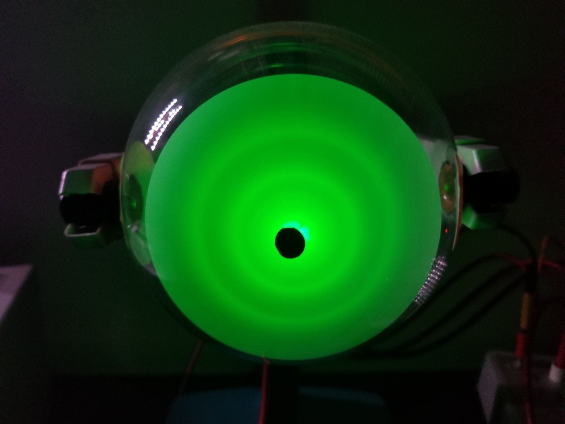
Figure 4: Electron diffraction pattern example
Explanation:
The diffraction rings are created by the electrons diffracting and interfering as they pass through the crystal structure of the carbon target. They behave like waves as they pass through the grating created by the graphite’s crystal structure. Deflecting the pattern with a magnet shows that the diffraction is produced by moving charged particles, rather than light or some other form of radiation. This shows both the particle and wave nature of electrons as they react to the magnetic field and pass through the graphite foil. When the voltage between cathode and anode is increased, the electrons diffract less and the rings get closer together. This shows that higher energy electrons have shorter wavelengths, which agrees with De Broglie’s formula.
Notes:
- Warm up the cathode for five to ten seconds before applying the high voltage
- Reduce the high voltage to zero before turning off the cathode heater
Written by Noah Peake