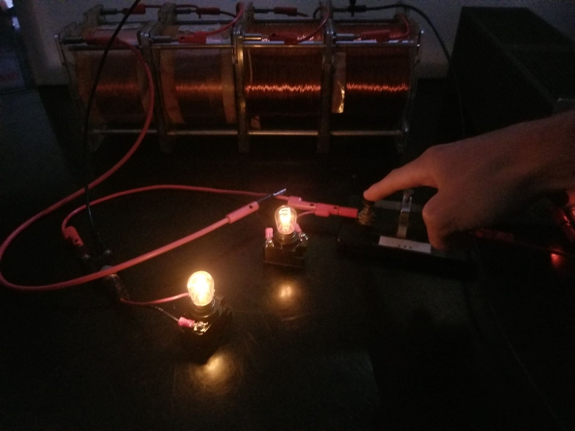
Figure 1: Steady state lamp in series with inductance
The lamp in series with inductance demonstrates the voltage drop across a large inductor when current is initially supplied. This is shown using one lamp in parallel with a lamp and inductor in series.To modulate current flow, a momentary switch is included in series with the whole setup. The lamp in series with the inductance begins emitting light visibly later than the lamp in series which helps visualize the voltage spike across the inductor immediately after receiving current.
Materials:
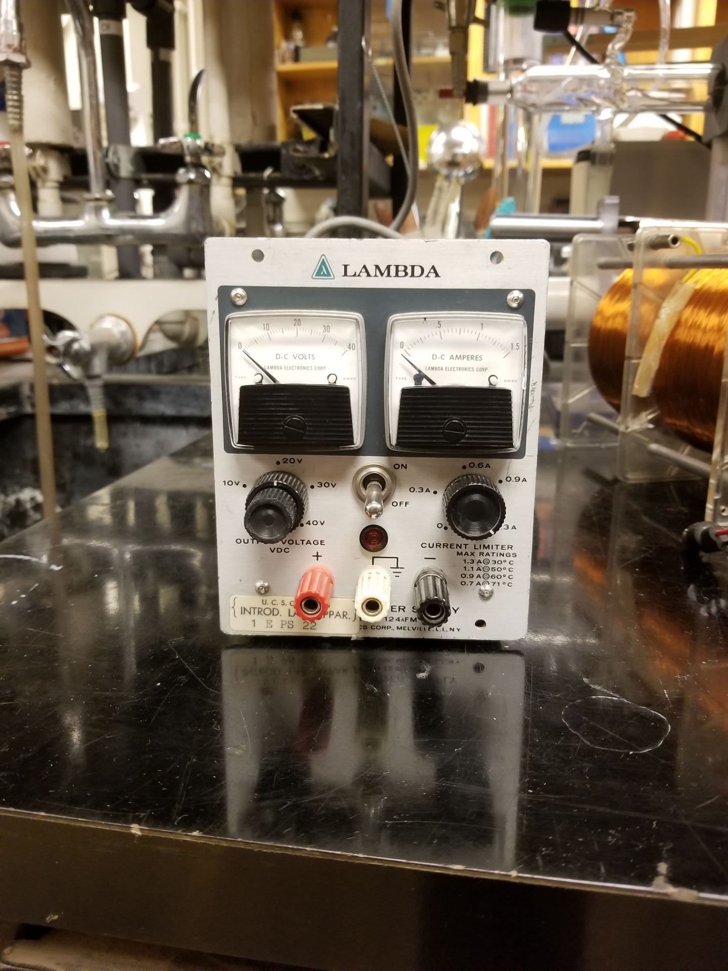
- Lambda Power supply [Cabinet K4]

Figure 2: Lambda power supply
- Four large coils [Cabinet F4]
- Large iron core (37cm high x 7.5cm diameter) [Cabinet F4]
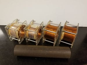
Figure 3: Induction coils and large iron core
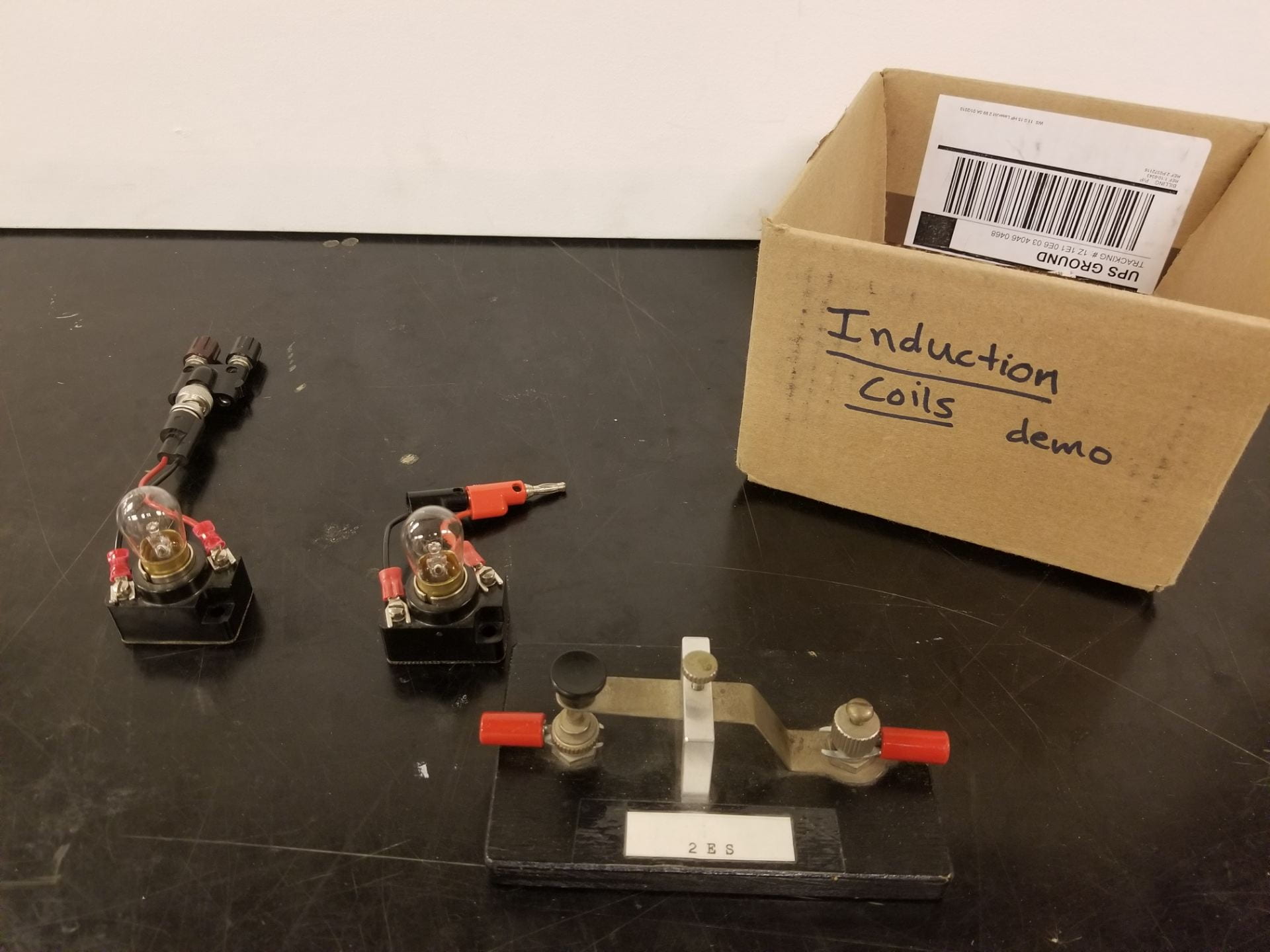
- Induction coils demo box [Cabinet F4]
- Momentary switch
- Two light bulbs
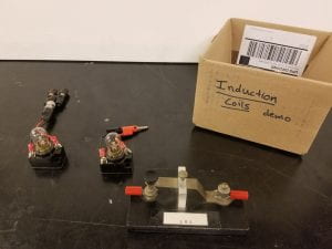
Figure 4: Induction coils demo box and contents
- Video camera for larger classes.

Setup:
The verbal explanation of this circuit setup can be found in the introduction at the top of the page. For clarity, a circuit diagram is provided below in Figure 5 along with the physical setup in Figure 6.
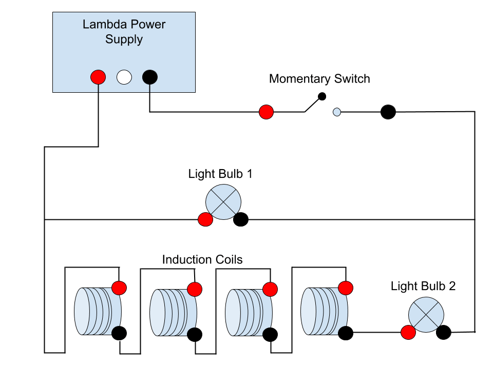
Figure 5: Setup circuit diagram
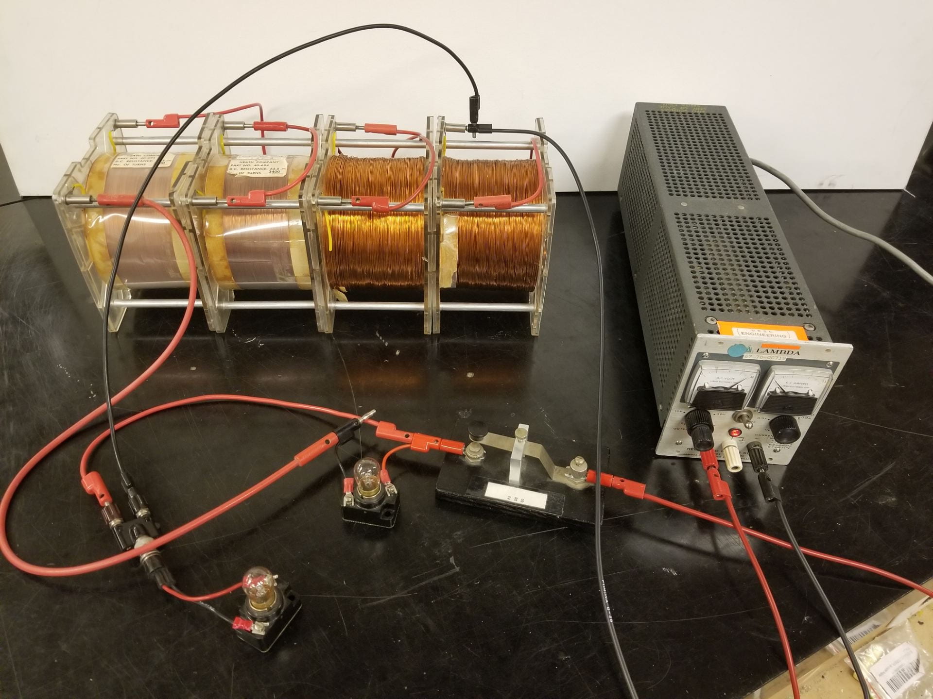
Figure 6: Physical setup
Demo:
To begin this demonstration, turn on the Lambda power supply. Set the voltage to 40 volts with a moderate amount of current. Insert the large iron core into the center of the induction coils wired in series to increase their inductance. Ensure that both lamps are clearly visible to the students. Then close the momentary switch by pushing down the movable tab, which completes the circuit and allow current to flow. With the switch held down, light bulb 1 in Figure 5 will illuminate instantly. Shortly after, less than a second, light bulb 2 will illuminate. Finally, release the momentary switch to cut the current supply to the circuit once again. Wait at least five seconds before closing the switch again or else the magnetic field within the inductors won’t have time to dissipate, and the time difference between bulb lightings won’t be noticeable.
Now remove the iron core from within the inductors, largely reducing their inductance. Then close the switch, which will cause both light bulbs to turn on at nearly the same time.
Explanation:
This demo revolves around the inductors and how their properties change when adding an iron core. We start by noting that iron is magnetic, meaning it contains many magnetic dipoles which can be aligned with an external magnetic field. As a result, the magnetic field requires more energy to build, but will be stronger due to these dipoles. To be specific, energy density stored in a magnetic field is

Now we combine this effect with the inductor by inserting the iron core into the center of the wire windings. Once current starts flowing through these windings the magnetic field begins to build. After a finite amount of time, the power from the Lambda power supply will finish building up the magnetic field. At this point, current flows through the inductor windings with only the inherent resistance of the copper to resist its flow.
We can now introduce this effect into the specific case of the circuit in Figure 5 for this demo. When the Lambda supply is switched on, power is delivered to both light bulb 1 and the series combination of inductor and light bulb 2. Light bulb 1 immediately receives the full voltage of the supply so it lights up instantly. However, the inductor draws nearly all of the power given to its branch in order to orient the iron dipoles. Once aligned, little power is dissipated by the copper wire and the rest is able to flow to light bulb 2. This effect can be seen as a slight time delay between illumination of light bulb 1 versus light bulb 2.
An alternate explanation for this effect can be found by considering the inductance, L, of the coil windings. Inserting the iron core into the inductor increases its inductance which has several consequences in our circuit. First, it is important to remember the equation describing back EMF produced by an inductor,

From this equation, we can see that the inductor will experience a large voltage spike when the switch is initially closed, because of the theoretically infinite 
Written by Noah Peake