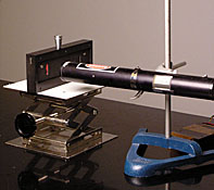
Figure 1: Common setup.
This demo creates a large (up to 10ft long) and brilliant single slit diffraction pattern from an adjustable thin slit salvaged from an old mass spectrometer.
Materials:
- 5mW laser [Cabinet H1]
- Rod, base, and clamp
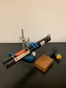
Figure 2: Class 3a laser on base, rod, and clamp assembly.
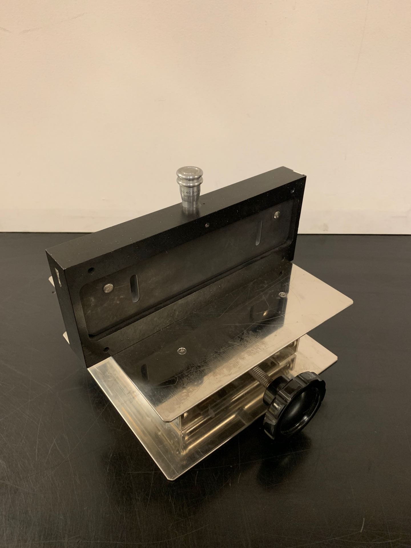
- Thin slit [Cabinet E3]
- Jack stand
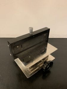
Figure 3: Thin slit on jack stand.

Demo:
- Assemble materials as shown in Figure 1, with a small (1-5cm) gap between the laser and thin slit apparatus and a blackboard size area onto which you can project the pattern.
- With the laser facing the thin slit, plug it in and wait for it to warm up and turn on. Then make adjustments to the laser and or slit to create the clearest diffraction pattern.
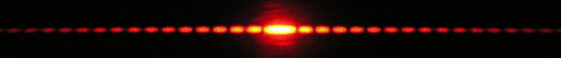
Figure 4: Possible diffraction pattern from demo.
Students can then see the spectacular bright red diffraction patterns when lights in the auditorium are dimmed.
Explanation:
When a plane wave of monochromatic (single wavelength) light encounters a single slit it can be treated as a set of point emitters via the Huygens–Fresnel principle, which states that:
“Every point on a wave-front may be considered a source of secondary spherical wavelets which spread out in the forward direction at the speed of light.”.
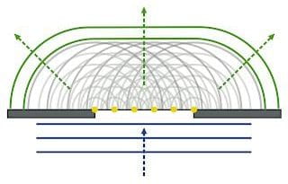
Figure 5: Visual of Huygens–Fresnel principal, from Wikimedia Commons.
The emissions from these points interact constructively in some areas, and destructively in others. Maximums in light intensity will form through constructive interference, while minimums come from destructive interference (Figure 6).

Figure 6: Constructive and destructive interference due to the interaction of waves from two point emitters from Cronodon.
Where the point emissions constructively and destructively interfere is related to their starting point along the slit, as that determines how far the emissions have to travel. Changes in the distance traveled by each emitted wave leads to varying degrees of phase changes with respect to other waves. A wave that is out of phase by λ/2 (half the wavelength) with another wave of the same λ will interact destructively as a trough will coincide with a peak, while waves in phase add constructively (Figure 7).
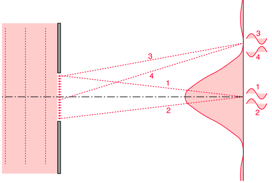
Figure 7: How waves from different point emitters can be in or out of phase, from Hyper Physics.
Notes:
- Exercise caution with where the laser is pointed.
- Make sure you know where the diffraction pattern goes, and do not look into it.
Written by Aleksander Beck