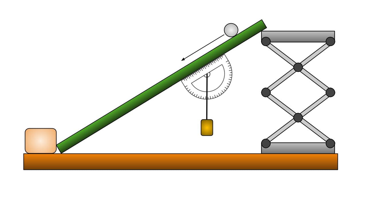
This demonstration shows constant acceleration under the influence of gravity, reproducing Galileo’s famous experiment. It can also be used in rotational dynamics [for a discussion on rotational dynamics, click here], to show and calculate moment of inertia, angular velocity, angular acceleration, and angular momentum.
This demonstration can also be used to show the static friction coefficients of different materials and how the force on an object will increase as the angle of the surface it lies on increases.
List of parts:
- Painted black wooden ramp
- Lab jack
- Two sandbags
- 50.8 mm diameter steel ball, mass 534.6 g
- Two stop clocks


Optional (to show angle of plane and related frictional effects)
- Giant protractor
- 2x small clamps to attach protractor to slope
- Plump bob/string (thin fishing line and 20g weight, found in blackboard mechanics)
- Friction block with different surfaces
Explanation:
Constant Acceleration:
To show constant acceleration with this demo it can be a good to mark out distances on the ramp and then have students time how long it takes for the ball to roll between the marks. They can use the time it takes for the ball to roll between the marks and from that calculate the acceleration at various different points on the ramp, which should all yield the same result (meaning the acceleration does not change with respect to time).
To calculate the acceleration of the ball, you can use the equation a = (V1 – V2)/t *. You will need to take eight different time measurements and will calculate four velocities and two accelerations. You can then compare the accelerations you calculate to see if the acceleration along the ramp stays constant (which it should). To do this you will want to mark out eight evenly spaced marks on the ramp and take note of the time that the ball crosses each mark (Image of what the ramp should look like below)
You can calculate Δt for each of the four segments of ramp with the equation:
Δt1 = t2 – t1
Δt2 = t4 – t3
And similarly for Δt3 and Δt4
Δx is the distance between the marked points. You don’t want them too long because you want to leave time for the ball to accelerate between where you are calculating velocities, so they should be between 10 and 15 cm each. The distance between the sets of marks does not make a difference to the final calculations.
Because we know that V = Δt/Δx, we can calculate the velocities across each distance Δx. This will yield V1, V2, V3, V4, which we can use to find two accelerations, a1, a2. to find the accelerations we use the equation:
a1 = (V1 – V2)/t
where t for a1, a2 are t4 and t8, respectively.
From these calculations we should find that a1 and a2 are equal (or near equal).
Friction:
This demo can also be used to show the relative static friction coefficients of different materials on wood. This demo is similar to the static and kinetic friction demo, but instead of changing the weight required to make the block move, we can change the angle of the plane. While the gravitational force acting on the block does not change depending on the angle of the board, a steeper incline will give a larger component force that is pushing the block down the ramp. This can be seen in the images below:
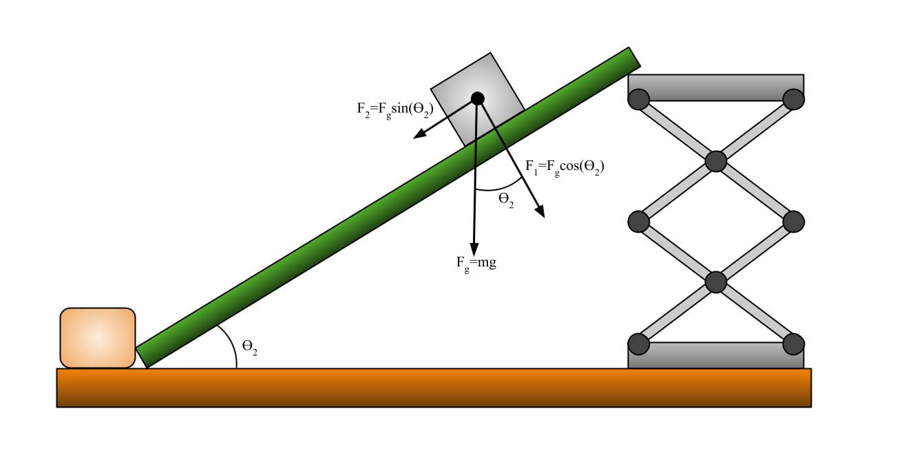
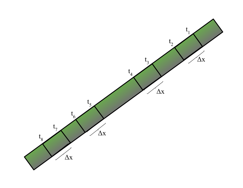
What the ramp should look like if marked for constant acceleration demonstrations, where the change in x should be equal across all four distances.
As seen above, a ramp with a larger θ (incline angle) will have a greater component force vector pushing it down the ramp (F2), and a smaller component force vector that is pushing it directly into the ramp (F1). Because there is a greater force pulling the block down the plane, a steeper incline will cause the block to begin descending when it may not have on a shallower incline. It is important to note here that the angle of the inclined plane will be the same as the angle between the force of gravity and the force perpendicular into the plane. It is with this angle that we measure the component forces, F1, and F2.
The coefficient of static friction (μ) of the block on the ramp will change magnitude of the force (F2) necessary to begin the block sliding. A greater μ will require a greater force (and therefore a steeper incline) to begin moving than a smaller μ. [For a more in-depth discussion on how the coefficient of friction changes the force required to begin moving an object, see the Static and Kinetic Friction demo, here.]
A greater force acting on the block can be created by increasing the angle (θ) of the ramp. This is because sin(θ) [when it is between the values 0 and (π/2)] will increase with an increasing θ. So we can easily seen that
If θ1 > θ2 then
Fgsinθ1 > Fgsinθ2
As F2 increases with increasing θ, it will allow blocks with greater coefficients of static friction to begin to slide down.
Notes:
- Make about a 10 cm height difference between the ends of the ramp.
- It is a good idea to have two students measure the travel time between marks on the ramp in order to calculate acceleration.
*This will take time and coordination so may not be feasible to do in a large introductory physics class, but may be well suited to a hands-on outreach demonstration at a local high school or middle school.
Written by Sophia Sholtz